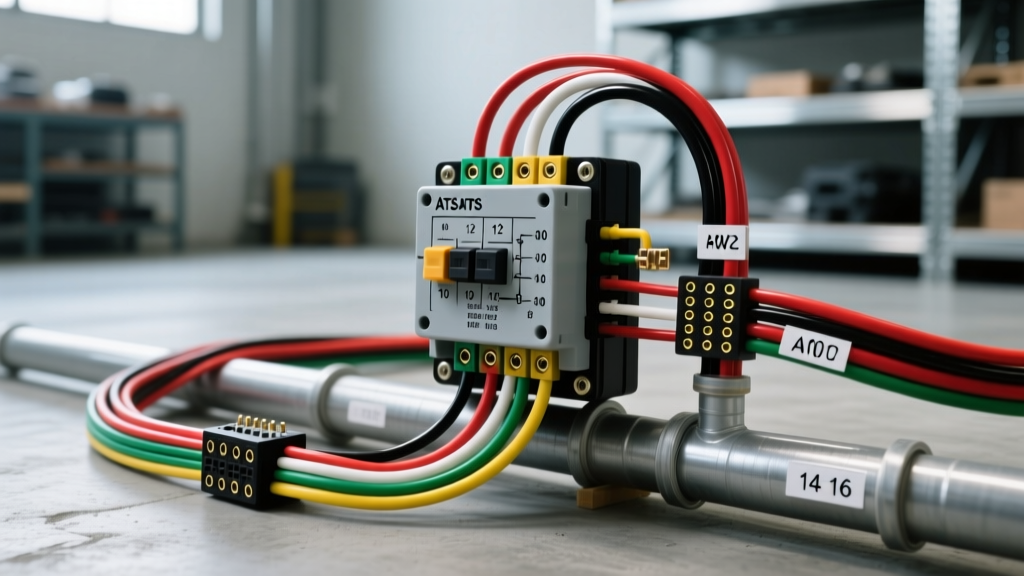
System Architecture: Integrating Shore, Generator, and Inverter Power
Upgrading a Class C RV, expedition truck camper, or custom Sprinter van from a manual generator inlet to an integrated Automatic Transfer Switch (ATS) is a hallmark modification for serious off-grid travelers. This upgrade eliminates the need to manually plug into an exterior generator inlet, allowing the onboard generator to seamlessly power the 120V AC main distribution panel and charge the house battery bank via the inverter/charger. However, executing this modification requires a precise understanding of AC power routing, DC auto-start control circuits, and the critical neutral-ground bonding rules outlined in the NFPA 1192 Standard on Recreational Vehicles.
When referencing a wiring diagram generator transfer switch setup for a mobile application, the architecture must handle three distinct power sources: Shore Power (30A or 50A), the Onboard Generator (typically 30A), and the Inverter/Charger. The ATS acts as the central logic and physical switching hub, prioritizing shore power when available, and automatically switching to the generator when shore power drops and the house battery voltage falls below a predetermined threshold.
The Neutral-Ground Bonding Dilemma in Mobile Applications
Before pulling any wire, you must address the neutral-ground bond. In a standard residential home, the neutral and ground are bonded at the main service panel. In an RV or camper van, the main distribution panel also bonds neutral and ground when connected to shore power. However, portable and onboard generators also have an internal neutral-ground bond at the alternator stator housing.
If you wire a standard ATS without accounting for this, you will create parallel neutral paths when the generator is running. This causes stray current to flow on the chassis ground, which will immediately trip GFCI receptacles, cause the inverter/charger to throw an Earth Fault or EPO (Emergency Power Off) code, and potentially create a shock hazard. To solve this, your wiring diagram must utilize a Switched Neutral ATS (which physically breaks and isolates the neutral connection between the generator and shore power) or you must remove the internal bonding screw inside the generator's junction box, treating the generator as a separately derived system. Always consult the Progressive Dynamics ATS Installation Manual for specific switched-neutral terminal configurations.
30A Generator Transfer Switch Wiring Diagram & AC Pinout
The following specification chart details the terminal block pinout for a standard 30A Switched-Neutral Automatic Transfer Switch. All AC wiring must utilize stranded copper THHN/THWN-2 or MTW (Machine Tool Wire) rated for 600V and 90°C.
| Terminal Label | Function | Wire Color (AC) | Wire Size (AWG) | Torque Spec |
|---|---|---|---|---|
| SHORE L1 | Shore Power Hot Input | Black | 10 AWG Stranded | 14 in-lbs |
| SHORE N | Shore Power Neutral Input | White | 10 AWG Stranded | 14 in-lbs |
| GEN L1 | Generator Hot Input | Black | 10 AWG Stranded | 14 in-lbs |
| GEN N | Generator Neutral Input | White | 10 AWG Stranded | 14 in-lbs |
| LOAD L1 | Main Panel Hot Output | Black | 10 AWG Stranded | 14 in-lbs |
| LOAD N | Main Panel Neutral Output | White | 10 AWG Stranded | 14 in-lbs |
| GROUND BUS | Chassis / Safety Ground | Green / Bare | 10 AWG Stranded | 20 in-lbs |
Note: If upgrading to a 50A system to support dual air conditioners, all L1/L2 Hot and Neutral wires must be upgraded to 6 AWG stranded copper, and torque specifications increase to 35 in-lbs per SAE J569 and NEC Article 551 standards.
DC Control Circuit: Integrating the Generator Auto-Start
The ATS does not start the generator on its own; it relies on a DC control signal sent to the generator's Engine Control Module (ECM). For popular onboard generators like the Cummins Onan MicroQuiet or HG series, this requires integrating a 2-wire auto-start relay or a smart controller like the Victron Energy Generator Starter.
The generator ECM typically uses a 6-pin or 4-pin Deutsch DT connector for remote signals. The wiring diagram for the DC control circuit is as follows:
- Pin A (12V+ BATT): Red, 14 AWG MTW. Connects to the house battery positive bus bar via a 15A inline ATC fuse.
- Pin B (GND): Black, 14 AWG MTW. Connects to the DC negative bus bar.
- Pin C (START SIGNAL): Yellow, 18 AWG. Connects to the ATS or Victron Generator Starter 'Start' relay output. Grounding this pin signals the ECM to crank.
- Pin D (STOP SIGNAL): Blue, 18 AWG. Connects to the 'Stop' relay output. Grounding this pin halts the engine.
When wiring the DC control harness, ensure it is routed at least 6 inches away from the 120V AC lines to prevent Electromagnetic Interference (EMI) from inducing false start/stop signals in the ECM logic board.
Wire Routing, Crimping, and Termination Best Practices
The most common cause of ATS failure in mobile environments is terminal arcing due to vibration-induced wire splaying. Standard wire strippers and screw terminals are insufficient for stranded THHN wire in a moving vehicle.
- Strip and Inspect: Strip exactly 1/2 inch of insulation. Inspect for nicked copper strands. If more than 10% of the strands are compromised, cut and re-strip.
- Ferrule Crimping: Slide an insulated bootlace ferrule (10 AWG / 6mm²) over the stranded wire. Use a ratcheting ferrule crimper to apply a square or hex crimp. This transforms the stranded wire into a solid pin, maximizing surface area contact inside the ATS screw terminal and preventing individual strands from escaping and causing short circuits.
- Ground Termination: All ground wires must be terminated using heat-shrink ring terminals (e.g., Molex Perma-Seal) crimped with an indent crimper, then bolted to the chassis ground bus bar using a star washer to bite through the paint and ensure a sub-0.1 ohm connection.
- Strain Relief: Secure all AC and DC cables within 4 inches of the ATS enclosure using adhesive-backed cable tie mounts and nylon zip ties to prevent vibration from transferring to the terminal blocks.
Troubleshooting Decision Tree: ATS and Generator Integration
Even with a perfect wiring diagram generator transfer switch installation, environmental factors and component tolerances can cause issues. Use this decision tree to diagnose common post-installation faults.
- Symptom: Inverter/Charger throws a 'Ground Fault' or 'EPO' error immediately upon generator start.
Cause: Double neutral-ground bond. The inverter detects current returning via the chassis ground instead of the neutral wire.
Fix: Verify the ATS is a Switched-Neutral model. If it is a standard ATS, locate the neutral-ground bonding screw or jumper wire inside the generator's alternator junction box and remove it to isolate the generator neutral. - Symptom: ATS contactor chatters, buzzes, or rapidly clicks during generator warm-up.
Cause: The generator voltage and frequency are unstable during the initial 10-second crank and warm-up phase, causing the ATS voltage-sensing relay to rapidly open and close.
Fix: Adjust the ATS 'Time Delay on Generator' (TDOG) potentiometer to 15-30 seconds, or install an external time-delay relay on the generator's 120V output line to prevent the ATS from sensing power until the voltage stabilizes above 110V AC. - Symptom: Generator cranks but will not start, or throws a Code 3 (Hard Start) on the Onan status light.
Cause: Voltage drop on the DC auto-start control circuit. The ECM is not seeing a clean ground reference on the Start pin due to undersized wire or a poor chassis ground.
Fix: Measure voltage drop across the DC start circuit while cranking. If the drop exceeds 0.5V, upgrade the control wire from 18 AWG to 14 AWG and clean the ECM ground point on the engine block. - Symptom: Shore power works, but ATS will not switch to generator; generator runs but AC outlets are dead.
Cause: Generator output breaker tripped, or the ATS 'GEN L1' terminal is loose.
Fix: Check the 30A breaker physically located on the generator's control box housing. If reset, use a multimeter to verify 120V AC at the ATS 'GEN L1' terminal. Retorque to 14 in-lbs.
For further technical validation regarding mobile electrical safety, grounding topologies, and overcurrent protection, always cross-reference your custom diagrams with the SAE International Mobile Electronics Standards and the specific OEM service manuals for your inverter and generator hardware.