The Danger of Mixing Household and RV Gas Fireplace Logic
When outfitting a Class A motorhome, a Sprinter camper conversion, or an overland expedition truck with a propane heating system, technicians and DIYers frequently search for a standard wiring diagram for gas fireplace installations. However, applying residential wiring logic to a mobile vehicular environment is one of the most dangerous mistakes you can make in automotive electrical integration. Residential gas fireplaces typically rely on 24V AC control transformers and 120V AC blower motors tied to a stable municipal grid. In contrast, RV and overland vehicle gas fireplaces operate on a volatile 12V DC battery bank and rely on delicate millivolt generators for flame rectification and pilot safety.
At Autoflowwire, we regularly diagnose melted wire harnesses, stalled blower motors, and dangerous propane leaks caused by misinterpreting vehicular gas fireplace schematics. This guide breaks down the critical safety warnings, common wiring mistakes, and exact AWG specifications required to safely integrate a gas fireplace into your vehicle's 12V DC electrical architecture while complying with vehicular safety standards.
Anatomy of an RV Gas Fireplace Wiring Diagram
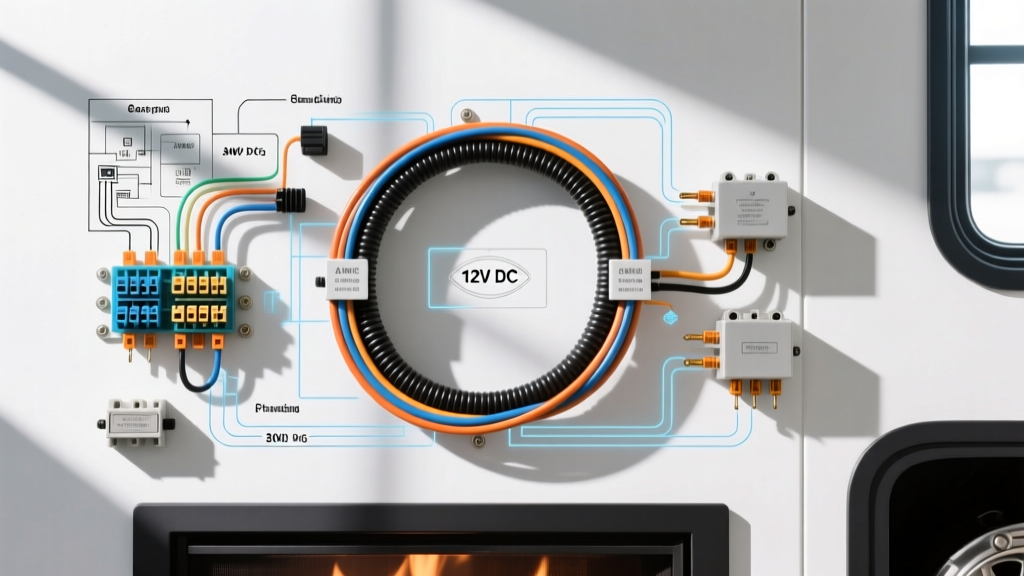
Unlike household units, an RV gas fireplace wiring diagram is split into two entirely isolated circuits: the Millivolt Control Circuit and the 12V DC Blower/Accessory Circuit. Understanding the boundary between these two systems is paramount for preventing catastrophic electrical fires or carbon monoxide hazards.
The Millivolt Generator and SIT Valve Pinouts
Most vehicular gas fireplaces utilize a SIT 820 Nova or Robertshaw 780-801 millivolt gas valve. This valve requires no external power to hold the pilot solenoid open; instead, it relies on a thermopile heated by the pilot flame to generate between 300mV and 750mV DC. The wiring diagram for this section involves extremely low voltage and high sensitivity to resistance.
- TH/TP (Thermostat/Thermopile): Connects to the 12V DC wall switch relay or thermostat control. When the switch closes, it diverts the millivolt current to open the main gas solenoid.
- TP (Thermopile): The dedicated return path for the thermopile generator.
- PILOT: Supplies the millivolt current to hold the pilot safety electromagnet open.
- GND (Ground): Must be bonded directly to the valve body or chassis star ground.
12V DC Blower Motor Circuit
The secondary circuit powers the convection blower motor, which pushes heated air into the vehicle cabin. This circuit draws directly from the vehicle's 12V DC fuse panel and is subject to high amperage loads, voltage drops, and intense vehicular vibration.
Top 4 Wiring Mistakes That Cause RV Fireplace Failures
Mistake 1: Undersized Blower Motor Wiring (Voltage Drop)
The most frequent error occurs when installers use 16 AWG or 18 AWG wire for the 12V DC blower motor circuit based on household low-voltage habits. A typical RV fireplace blower motor draws between 2.5A and 4.5A. If you run 16 AWG wire over a 15-foot distance from the DC fuse panel to the fireplace, you will experience a voltage drop of approximately 1.6V. If your alternator is resting at 12.2V, the motor receives only 10.6V. This causes the blower to stall, draw locked-rotor current, and overheat the wire harness, creating a severe fire hazard. Correction: Always use a minimum of 12 AWG stranded copper wire for the blower motor power and ground runs to ensure the motor receives at least 11.5V under load.
Mistake 2: Introducing Resistance into the Millivolt Circuit
The thermopile generates less than 1 volt. Any added resistance in the wiring diagram for gas fireplace control circuits will cause the pilot solenoid to drop out, shutting off the gas supply. Installers often use standard wire nuts or cheap automotive spade connectors to extend the thermopile leads. Oxidation and vibration will quickly increase resistance at these junctions. Correction: Never use wire nuts in an RV. Use high-temperature ring terminals, star washers, and dielectric grease on all millivolt connections. If wire extension is absolutely necessary, use continuous runs of 18 AWG high-strand-count silicone wire.
Mistake 3: Using Solid Core Wire in a High-Vibration Environment
Residential electricians often reach for solid-core Romex or thermostat wire when wiring RV appliances. In a moving vehicle, the constant chassis vibration and road shock will cause solid-core wire to work-harden, fatigue, and eventually snap inside the insulation. This can lead to a short circuit against the metal fireplace chassis or a loss of the safety interlock ground. Correction: Adhere strictly to the SAE J1128 Low Tension Primary Cable Standard, which mandates the use of multi-strand, cross-linked polyethylene (XLPE) or PVC-insulated automotive wire for all vehicular DC applications.
Mistake 4: Daisy-Chaining Grounds to the Gas Line
A dangerous shortcut involves grounding the 12V DC blower motor to the copper or aluminum propane supply line, or daisy-chaining the ground to the fireplace's outer sheet metal skin. Propane lines are not designed to carry electrical fault currents, and sheet metal skins often have poor conductivity due to powder coating or paint. Correction: Run a dedicated 12 AWG ground wire directly from the blower motor to a verified, bare-metal chassis star ground point, treating the connection with anti-corrosion compound.
Technical Specification Table: RV Fireplace Wiring Standards
| Circuit Function | Recommended AWG | Wire Type / Standard | Standard RV Wire Color Code | Connector Type |
|---|---|---|---|---|
| Blower Motor 12V+ Feed | 12 AWG | SAE J1128 Stranded (GXL/TXL) | Red | Deutsch DT or Insulated Ring |
| Blower Motor 12V- Ground | 12 AWG | SAE J1128 Stranded (GXL/TXL) | Black | Chassis Star Ground Ring |
| 12V Wall Switch / Thermostat Trigger | 16 AWG | SAE J1128 Stranded | White or Yellow | Sealed Quick-Disconnect |
| Thermopile to SIT Valve (Millivolt) | 18 AWG (High Strand) | High-Temp Silicone / Teflon | Copper / Bare / High-Temp White | High-Temp Ring / Spade |
| Thermal Safety Interlock (Limit Switch) | 14 AWG | High-Temp Fiberglass Braided | Blue or Orange | High-Temp Ceramic Wire Nuts |
Troubleshooting the Thermopile and Control Valve Pinouts
When your RV gas fireplace fails to ignite or the pilot drops out when the main burner fires, the issue is almost always traceable to a wiring fault in the millivolt diagram. Use a digital multimeter (DMM) capable of reading millivolts (mV) to perform this decision tree:
- Step 1: Open-Circuit Thermopile Test. Disconnect the thermopile wires from the SIT valve TP and TH/TP terminals. Light the pilot manually. Measure the voltage across the disconnected thermopile leads. A healthy thermopile will read between 550mV and 750mV DC. If it reads below 350mV, the thermopile is degraded, or the pilot flame is not fully engulfing the upper third of the generator.
- Step 2: Closed-Circuit (Load) Test. Reconnect the wires to the valve. With the pilot lit and the wall switch OFF, measure the voltage between the TH/TP and TP terminals. It should read roughly half of the open-circuit voltage (e.g., 300mV - 400mV). This voltage is what holds the pilot solenoid open.
- Step 3: Voltage Drop Under Main Burner Load. Turn the wall switch ON to open the main gas valve. The voltage at the TH/TP terminal will drop further as the main solenoid engages. If the voltage drops below 120mV, the pilot solenoid will starve, and the entire fireplace will shut down. This confirms excessive resistance in your wiring harness, a failing wall switch, or a poor chassis ground.
Safety Warnings & NFPA 1192 Compliance
Integrating gas and electricity in a confined vehicular space requires strict adherence to safety codes. The NFPA 1192 Standard on Recreational Vehicles and guidelines from the Recreational Vehicle Industry Association (RVIA) mandate specific clearances and wiring protections for gas appliances.
- High-Temperature Clearances: Any wiring diagram for gas fireplace installations must account for ambient heat. Standard PVC-insulated automotive wire will melt and short out if routed too close to the fireplace firebox or exhaust flue. Always use high-temperature fiberglass-braided or silicone-insulated wire within 18 inches of the combustion chamber.
- Fuse Protection: The 12V DC blower motor circuit must be protected by an inline ATO/ATC blade fuse or a marine-grade circuit breaker rated at 125% of the motor's maximum continuous amperage draw, located within 18 inches of the battery positive terminal.
- Carbon Monoxide Interlocks: Modern overland and RV builds should wire the fireplace 12V control circuit through a relay that is disabled if the vehicle's LP/CO detector triggers an alarm, preventing the blower from circulating dangerous gases if the exhaust flue is compromised.
By respecting the unique electrical demands of mobile gas appliances and avoiding residential wiring shortcuts, you ensure your vehicle's heating system remains safe, reliable, and compliant with automotive electrical standards.