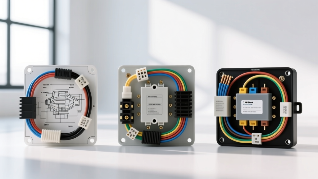
The Problem with Generic LED Lighting Diagrams
When upgrading your truck or SUV with auxiliary illumination, searching for a generic wiring diagram for LED lights often leads to frustrating results. Modern vehicle electrical systems are not simple 12-volt DC loops; they are complex, multiplexed networks managed by a Body Control Module (BCM). Connecting a high-draw LED light bar directly to a factory headlight circuit or using an outdated relay harness on a modern CANbus vehicle will result in flickering, hyper-flashing, blown fuses, or permanent BCM damage.
As an automotive electrical specialist, I frequently see off-road enthusiasts struggle because they selected the wrong harness architecture for their specific vehicle year and make. This guide compares the three primary harness types—Standard Relay, CANbus/PWM Anti-Flicker, and Heavy-Duty Dual-Output—providing the exact wiring diagram for LED lights you need based on your vehicle's electrical topology, complete with AWG specifications, DIN relay pinouts, and connector requirements.
1. Standard 30A Relay Harness (Pre-2015 Vehicles)
The standard 30A relay harness is the baseline wiring diagram for LED lights on older vehicles (typically pre-2015) that utilize traditional analog 12V switching for exterior lighting. Vehicles like the 2003-2013 Chevrolet Silverado or 2007-2014 Ford F-150 (non-LED factory headlights) supply a constant 12V analog signal when the headlight switch is actuated. This constant voltage is perfect for triggering a standard Bosch-style automotive relay.
DIN 72552 Relay Pinout Configuration
Understanding the relay is critical. The standard wiring diagram for LED lights utilizing a Bosch-style relay follows the DIN 72552 numbering standard. Below is the pinout and wire color mapping for a typical 30A setup:
| Pin Number | Function | Wire Gauge (AWG) | Standard Wire Color | Connection Point |
|---|---|---|---|---|
| 30 | Common (Power In) | 12 AWG | Red | Direct to Battery (+) via Inline 30A Fuse |
| 87 | Normally Open (Power Out) | 12 AWG | Red/White Stripe | To LED Light Bar (+) Input |
| 85 | Coil Ground | 16 AWG | Black | To Chassis Ground or Battery (-) |
| 86 | Coil Trigger (Switch) | 16 AWG | Yellow | To Factory Headlight (+) or Toggle Switch |
Expert Insight: Never use 14 AWG or 16 AWG for Pins 30 and 87 if the run from the battery to the front bumper exceeds 8 feet. According to SAE J1128 Low Tension Primary Cable standards, voltage drop over distance will starve the LED drivers, causing reduced lumen output and premature driver failure. Always use stranded, multi-strand copper (not Copper Clad Aluminum - CCA) for the main power feed.
2. CANbus and PWM Anti-Flicker Harness (2015+ Modern Trucks)
If you drive a 2015+ Ford F-150, 2018+ Jeep Wrangler JL, or a modern Ram 1500, the standard wiring diagram for LED lights will fail. These vehicles use Pulse Width Modulation (PWM) to monitor bulb health and control lighting. Instead of a steady 12V signal, the BCM sends a rapid square-wave signal (pulsing between 0V and 12V hundreds of times per second) to check for circuit continuity. Because LED light bars draw significantly less current than halogen bulbs, the BCM interprets the low draw as a 'blown bulb' and cuts power, resulting in severe strobing or a complete shutdown of the circuit.
The Anti-Flicker Capacitor Module
To solve this, the CANbus wiring diagram for LED lights incorporates an inline anti-flicker module (a large capacitor and resistor bank) placed between the factory trigger wire and the relay coil (Pin 86). This module absorbs the PWM pulses and releases a steady, smoothed 12V analog signal to trigger the relay.
- Trigger Wire Connection: Splice the 18 AWG trigger wire into the factory headlight positive circuit.
- Module Placement: Mount the capacitor module in the engine bay, away from exhaust manifolds (max operating temp is usually 85°C).
- Resistor Load: Some advanced harnesses include a parallel 10-ohm, 50W power resistor to artificially increase the current draw, tricking the BCM into recognizing a standard 55W halogen bulb.
3. Heavy-Duty Dual-Output Harness (High-Draw Arrays)
When running multiple LED pods, rock lights, and a 50-inch light bar simultaneously, a single 30A relay is insufficient. The heavy-duty wiring diagram for LED lights utilizes either a single 40A/50A relay with dual '87' output pins or two separate 30A relays triggered by a single low-amperage switch.
Dual 87-Pin Relay Architecture
Heavy-duty relays feature five pins: 30, 85, 86, 87, and 87a (or a second 87). For high-draw LED arrays, you must use a relay with two 87 pins (Normally Open). This allows you to run two independent 12 AWG power lines to separate lighting zones (e.g., Zone A for the roof bar, Zone B for the bumper pods) while sharing a single 40A main power feed from the battery using 10 AWG wire. Littelfuse automotive relay specifications dictate that continuous loads should not exceed 80% of the relay's rated capacity; therefore, a 40A relay should only handle a sustained 32A load.
Product Comparison Matrix: Selecting Your Harness
| Harness Type | Max Sustained Draw | Main Power AWG | Trigger Type | Best Vehicle Application |
|---|---|---|---|---|
| Standard 30A Relay | 24 Amps | 12 AWG | Analog 12V | Pre-2015 Trucks, Classic SUVs, UTVs |
| CANbus Anti-Flicker | 24 Amps | 12 AWG | PWM / Multiplexed | 2015+ F-150, 2018+ Jeep JL, Modern Ram |
| Heavy-Duty Dual 40A | 32 Amps (per circuit) | 10 AWG | Analog 12V (via secondary switch) | Off-Road Race Trucks, Multi-Light Arrays |
Connector Selection: Deutsch DT vs. ATP
The wiring diagram for LED lights is only as reliable as its weakest connection point. Soldering and heat-shrinking wires in an engine bay or undercarriage is highly discouraged due to vibration-induced fatigue and moisture intrusion. You must use sealed automotive connectors.
Deutsch DT Series (Industry Standard)
Premium LED manufacturers (like Baja Designs and Rigid Industries) use the 2-pin Deutsch DT connector. Rated for 13 amps per contact (continuous), these connectors feature silicone rear seals and a thermoplastic housing. Technical Requirement: You must use a specialized crimping tool (such as the HDT-48) to properly compress the nickel-plated copper contacts onto 16-20 AWG wire. An improper crimp will lead to high resistance and localized melting.
ATP Connectors (Budget Alternative)
ATP connectors are physically compatible with Deutsch DT receptacles but are manufactured from lower-grade nylon. While acceptable for low-draw LED rock lights (under 5 amps), they should not be used for primary roof-mounted light bars drawing near the 13A continuous limit, as the housing can deform under high thermal loads.
Real-World Troubleshooting Decision Tree
When your LED lighting setup fails, follow this diagnostic sequence before replacing components:
- Symptom: Light bar flickers rapidly when turned on.
- Cause: PWM signal from factory BCM without an anti-flicker capacitor.
- Fix: Install a CANbus PWM decoder module inline with the trigger wire (Pin 86).
- Symptom: Lights dim significantly when the vehicle is idling but brighten when revving.
- Cause: Severe voltage drop on the main power or ground circuit, often due to undersized wire or a poor chassis ground.
- Fix: Upgrade Pin 30 and Ground wires to 10 AWG. Remove paint from the chassis ground point and secure with a star washer and anti-corrosion dielectric grease.
- Symptom: Relay clicks rapidly and gets hot to the touch.
- Cause: The relay coil is receiving an undervoltage condition or the contacts are arcing due to an inductive spike from the LED drivers.
- Fix: Install a flyback diode (1N4001) across Pins 85 and 86 (stripe facing Pin 86) to suppress inductive voltage spikes, protecting the relay coil and BCM switch.
Final Routing and Looming Best Practices
Once you have selected the correct wiring diagram for LED lights and assembled your harness, routing is critical. Never zip-tie wiring directly to steering shafts, exhaust components, or sharp metal brackets. Always pass wires through the firewall using existing rubber grommets, applying silicone spray to ease the wire through without tearing the seal. Use split-loom tubing (corrugated plastic) over all wires routed under the hood, and secure the loom with adhesive-backed P-clips every 12 inches. For ultimate protection against rodent chewing and abrasion, wrap the split-loom in Tesa cloth automotive wiring tape. For more in-depth vehicle-specific BCM pinouts and multiplexing guides, refer to Hella's technical automotive lighting resources and your vehicle's specific factory service manual.