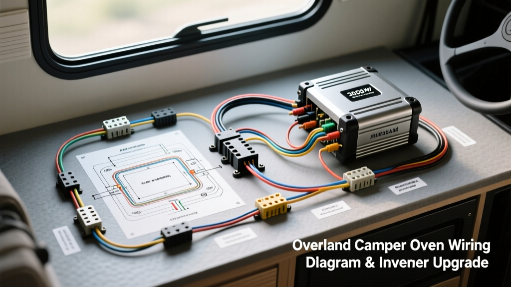
The Overland Galley Challenge: High-Draw Convection Ovens
Upgrading an expedition vehicle or overland camper van to include a full galley often culminates in the installation of a 120V convection oven or microwave-oven combo. Unlike LED lighting or water pumps, a standard 120V convection oven features a massive resistive heating element that pulls between 1500W and 1800W continuously. When mapping out your vehicle's electrical architecture, this single appliance will dictate the scale of your entire power system. A poorly executed install will result in severe voltage sag, tripped breakers, or worse, a chassis fire.
This guide provides a comprehensive upgrade pathway and the foundational logic for your 120V AC wiring diagram, oven circuit routing, and DC-side inverter integration. We will focus on a 3000W Pure Sine Wave inverter upgrade paired with a high-capacity Lithium Iron Phosphate (LiFePO4) battery bank, adhering to strict automotive and marine electrical standards.
Sizing the Inverter and Battery Bank for Oven Loads
To run an 1800W oven, you must calculate the DC amperage draw from your battery bank. Using the formula Watts / Volts = Amps, an 1800W load on a 12V nominal system (which often sits around 13.2V) draws roughly 136 amps. However, inverters are not 100% efficient. Assuming an 85% efficiency rating, the actual DC draw jumps to approximately 160 amps. Furthermore, the initial inrush current to energize the oven's control board and relay can spike 20% higher for a fraction of a second.
A 2000W inverter will immediately trip its internal overload protection. You must upgrade to a 3000W Pure Sine Wave Inverter (such as the Victron MultiPlus II). Additionally, your LiFePO4 battery bank must possess a Battery Management System (BMS) capable of sustaining a continuous 200A discharge. A standard 100Ah drop-in battery will shut down instantly; a 400Ah parallel bank or a single 200Ah high-discharge server-rack battery is mandatory.
DC Side: Battery to Inverter Specifications
The most common failure point in overland oven upgrades is undersized DC cabling. When 160 amps flow through a wire, resistance generates heat. According to SAE J1171 standards for marine and automotive electrical systems, wires routed through engine bays or insulated compartments must be derated for heat. We specify 4/0 AWG tinned copper welding cable for runs up to 10 feet to keep voltage drop below 1%.
DC Wiring Specification Chart
| Component | Specification | Notes / Torque |
|---|---|---|
| DC Cable | 4/0 AWG Tinned Copper (Red/Black) | Stranded, high-flex for vehicle vibration |
| Main Fuse | 250A Class T (Littelfuse) | Must be within 7 inches of battery positive |
| Terminals | 5/16' Tinned Copper Ring | Dual-wall adhesive heat shrink required |
| Busbar Connection | 3/8' Stainless Steel Stud | Torque to 15 ft-lbs with anti-oxidant paste |
| Inverter Lugs | M8 or 5/16' depending on model | Torque to 10-12 ft-lbs (check manual) |
AC Side: Drafting the 120V Wiring Diagram
When drafting your 120V AC wiring diagram, oven circuits must be isolated from general-purpose receptacles. A convection oven requires a dedicated 20A circuit. While standard residential code allows 12 AWG wire for 20A circuits, the high ambient temperatures inside an overland rig's cabinetry and the potential for long wire runs dictate an upgrade to 10 AWG THHN/THWN stranded copper.
AC Circuit Breaker and Wire Match
| Wire Color (AC) | Function | Gauge | Breaker Rating |
|---|---|---|---|
| Black | Line (Hot) | 10 AWG Stranded | 20A GFCI/AFCI |
| White | Neutral | 10 AWG Stranded | N/A (Tied to Neutral Bus) |
| Green | Equipment Ground | 10 AWG Stranded | N/A (Tied to AC Ground Bus) |
Critical Expert Note on Neutral-Ground Bonding: Many high-end convection ovens feature internal EMI (Electromagnetic Interference) filters that intentionally leak a small amount of current to the equipment ground. If your inverter has an internal Neutral-Ground bonding relay (common in Victron and Xantrex units) AND you have also bonded the neutral to ground at your AC sub-panel, the GFCI breaker will detect this as a ground fault and trip immediately when the oven turns on. Your wiring diagram must ensure that the Neutral and Ground are bonded only at the inverter, and kept strictly isolated on the AC breaker busbar.
Step-by-Step Modification Procedure
- Disconnect and Isolate: Remove the negative terminal from the vehicle's starter battery and the main fuse from the house battery bank. Verify zero voltage at the inverter DC terminals using a multimeter.
- Prepare 4/0 AWG DC Cables: Strip exactly 7/8' of insulation from the 4/0 cable. Insert the tinned copper ring terminal and crimp using a 6-ton hydraulic crimper with the correct 4/0 die. The crimp should require 150+ lbs of pull force to separate.
- Seal the Terminals: Slide 3/4' dual-wall adhesive heat shrink over the crimp barrel. Apply heat evenly until the internal adhesive oozes slightly from the edges, creating a waterproof, vibration-proof seal against galvanic corrosion.
- Install the Class T Fuse: Mount the 250A Class T fuse holder on the positive battery cable, no more than 7 inches from the battery terminal. This protects the entire 4/0 run in the event of a dead short against the chassis.
- Route AC Wiring: Run the 10 AWG Black, White, and Green wires from the inverter's AC OUT terminal block to your dedicated AC sub-panel. Use split-loom tubing where the wires pass through metal bulkheads or cabinetry to prevent chafing.
- Terminate the Oven Receptacle: Install a heavy-duty NEMA 5-20R or standard 20A tamper-resistant GFCI receptacle behind the oven housing. Torque the terminal screws to 14 in-lbs to prevent arcing under high thermal load.
Expert Troubleshooting: Oven Failure Modes
Even with a perfect wiring diagram, oven modifications in 12V environments present unique electrical anomalies. Use this decision tree to diagnose issues:
- Symptom: Oven display turns on, but the moment the heating element engages, the inverter shuts down and throws an overload alarm.
Cause: Voltage sag on the DC side. The battery bank cannot deliver the 160A surge, causing DC voltage to drop below the inverter's low-voltage cutoff (usually 10.5V).
Fix: Check for loose 4/0 AWG lugs. Verify the BMS continuous discharge rating. Upgrade battery interconnect cables to match the 4/0 main runs. - Symptom: Oven GFCI receptacle trips instantly upon plugging in the appliance, even when the oven is off.
Cause: Double Neutral-Ground bonding. The inverter's internal transfer switch is bonding N-G, and the AC sub-panel is also bonded.
Fix: Remove the green bonding screw or jumper wire on the AC sub-panel's neutral busbar. The bond must exist exclusively inside the inverter chassis. - Symptom: Oven heats extremely slowly, and food takes twice as long to bake.
Cause: The inverter is outputting a Modified Sine Wave, or the AC wire run is too long and undersized, causing the voltage at the receptacle to drop to 105V under load. Resistive heating elements lose power exponentially with voltage drops (P = V^2 / R).
Fix: Verify the inverter is a Pure Sine Wave model. Measure AC voltage at the receptacle while the oven is running. If below 115V, upgrade the AC wiring from 12 AWG to 10 AWG or shorten the run.
Final Inspection and Compliance
Before sealing the cabinetry, perform a thermal scan. Turn the oven on to its maximum temperature (450°F) and let it cycle for 30 minutes. Use an infrared thermometer to check the 4/0 AWG DC lugs, the Class T fuse, and the AC breaker. No terminal should exceed 120°F (49°C). If a lug is hot to the touch, it indicates a poor crimp or insufficient torque. For comprehensive standards on AC/DC integration in mobile environments, consult the ABYC E-11 AC and DC Electrical Systems guidelines, which serve as the gold standard for high-end expedition vehicle builds. Proper execution of this wiring diagram ensures your galley oven will perform flawlessly, whether you are parked at a trailhead or deep in the backcountry.