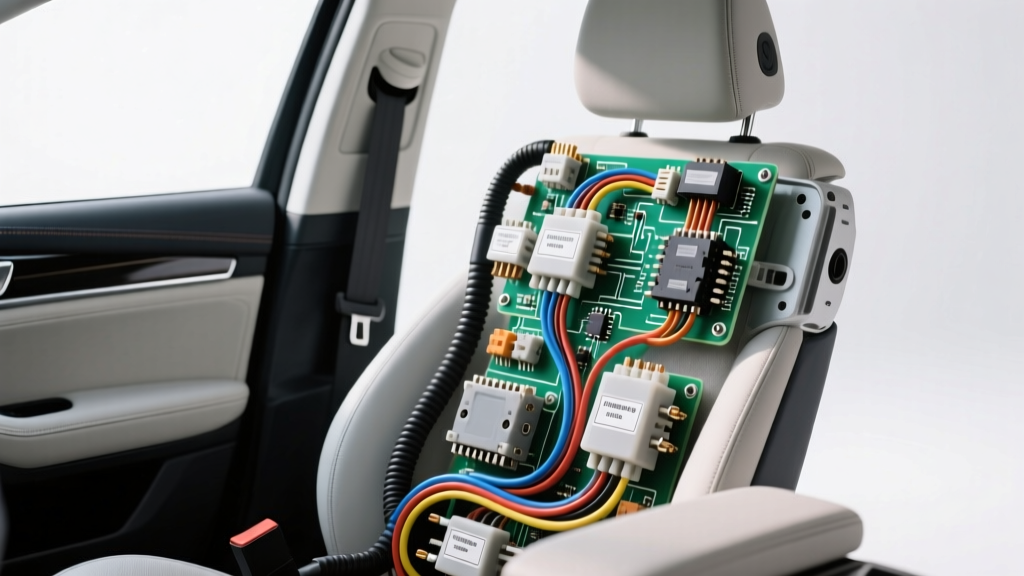
Architecting the 12V Mobility System: Lift and Recliner Integration
Integrating a rear hydraulic wheelchair lift and a front power transfer seat (electric recliner base) into a vehicle's 12V DC electrical system requires meticulous planning. When sourcing the correct lift wiring diagram for electric recliner seat bases and rear platform deployments, technicians must account for high-amperage inductive loads, polarity reversal for linear actuators, and strict voltage drop thresholds. In mobility van conversions—such as those performed on the Chrysler Pacifica or Dodge Grand Caravan—the factory alternator and chassis grounding points are rarely sufficient to handle the simultaneous draw of a 60A hydraulic lift pump and dual 15A recliner actuators without causing ECU reset faults or severe voltage sag.
This guide provides a comprehensive cost and tool requirements analysis for executing a flawless mobility lift and electric recliner installation. We will break down the exact schematic logic, required AWG ratings, SAE-compliant wire color codes, and the specialized crimping tools necessary to ensure long-term reliability in high-vibration automotive environments.
Schematic Overview: Dual-Motor Control Logic
A proper lift wiring diagram for electric recliner systems separates the high-current hydraulic pump circuit from the sensitive solid-state control modules of the power seat base. The system utilizes a secondary deep-cycle AGM battery isolated via a 200A continuous-duty solenoid. The lift platform relies on a 40A Bosch-style SPDT relay to trigger the hydraulic solenoid, while the electric recliner seat base utilizes an H-Bridge motor controller or a bank of DPDT (Double Pole Double Throw) relays to reverse polarity, allowing the linear actuators to extend and retract smoothly.
Essential Tool Requirements for High-Amp Mobility Wiring
Executing this wiring schematic requires more than basic side cutters. Automotive electrical standards dictate the use of calibrated crimping and testing tools to prevent high-resistance connections, which are the leading cause of thermal runaway in mobility lifts.
- Hydraulic or Ratcheting Wire Crimpers: Required for 6 AWG to 2 AWG ring terminals. Ratcheting mechanisms ensure the exact compression ratio specified by the terminal manufacturer.
- Deutsch DT Crimp Tool & Pin Insertion Tool: Essential for terminating the 12 AWG and 14 AWG wires connecting the electric recliner actuators to the DPDT relay bank.
- Digital Multimeter with Min/Max Hold: Used to measure voltage drop across the chassis ground and verify the 120mV maximum drop threshold on 12V control circuits.
- Heat Gun with Reflector Nozzle: For shrinking dual-wall, adhesive-lined heat shrink tubing (minimum 3:1 shrink ratio) to seal out moisture and road salt.
- Torque Wrench (Inch-Pounds): Anderson Powerpole SB50 connectors and distribution block lugs must be torqued to exactly 120 in-lbs to prevent arcing under the 60A load of the lift motor.
Component & Cost Analysis Breakdown
Budgeting for a mobility conversion requires understanding the difference between commercial-grade and consumer-grade electrical components. Below is a cost analysis for a professional-grade lift and electric recliner wiring harness.
| Component Category | Specification / Rating | Est. Cost (USD) | Function in Schematic |
|---|---|---|---|
| Marine-Grade Tinned Copper Wire | 4 AWG (Red/Black) | $85.00 | Main power feed from secondary battery to distribution block |
| Actuator Control Wire | 12 AWG (SAE J1128) | $35.00 | Polarity-reversing feed to electric recliner linear actuators |
| DPDT Automotive Relays | 40A, 12V DC, Sealed | $45.00 (Set of 4) | H-Bridge logic for recliner up/down and recline/return functions |
| Anderson Powerpole Connectors | SB50 (2-Pole) | $28.00 | Quick-disconnect for lift platform maintenance and battery isolation |
| Deutsch DT Receptacles | 2-Pin & 4-Pin | $40.00 | Weatherproof connections at the electric recliner seat base pivot points |
| Resettable Circuit Breakers | 60A & 30A (Surface Mount) | $55.00 | Overcurrent protection for lift pump and seat base control modules |
| Adhesive-Lined Heat Shrink | Assorted (3:1 Ratio) | $25.00 | Environmental sealing for all ring terminals and splices |
Note: Labor costs for routing wire through vehicle B-pillars and under floor pans typically add $400 to $800 depending on the chassis complexity.
Pinout Configurations and OEM Wire Color Codes
Adhering to SAE J1128 standards for wire color codes ensures that future technicians can safely troubleshoot the system. The following color codes and pinouts apply to the DPDT relay bank controlling the electric recliner seat base.
DPDT Relay Pinout for Recliner Actuator (Polarity Reversal)
To make a linear actuator extend and retract, the polarity of the 12V supply must be swapped. This is achieved using two DPDT relays wired in an H-Bridge configuration.
- Pin 30 (Common): 12V+ Input (Red, 12 AWG) from the 30A resettable breaker.
- Pin 87a (Normally Closed): Ground (Black, 12 AWG) routed to the chassis ground bus bar.
- Pin 87 (Normally Open): Motor Feed (Yellow or Blue, 12 AWG) routed to the Deutsch DT connector at the recliner actuator.
- Pin 86 (Coil +): Switched 12V+ (White, 18 AWG) from the driver's momentary toggle switch.
- Pin 85 (Coil -): Ground (Black, 18 AWG) to the seat base ground lug.
When the toggle switch is pressed in the 'Recline' direction, Relay A energizes, sending 12V+ to Actuator Pin 1, while Relay B remains de-energized, grounding Actuator Pin 2. Reversing the switch swaps the states, reversing the motor.
Lift Platform Limit Switch Integration
The hydraulic lift diagram must include micro-switch limit sensors to prevent the pump from dead-heading. These sensors utilize 18 AWG Green (Signal) and Black (Ground) wires. If the limit switch fails to open at full deployment, the hydraulic pump will overheat. Always wire limit switches on the ground side of the relay coil (Pin 85) to ensure the circuit breaks safely without leaving the main power feed energized.
Troubleshooting Voltage Drop and Actuator Failure
When a mobility lift operates sluggishly or an electric recliner seat base stutters during adjustment, the issue is rarely a failed motor. According to guidelines published by the National Mobility Equipment Dealers Association (NMEDA), 80% of mobility electrical failures are traced to high-resistance grounding points and undersized wiring.
Symptom-Cause-Fix Decision Tree
- Symptom: Lift motor clicks, but the platform does not raise. Voltage at the battery reads 12.6V, but voltage at the motor terminals drops to 8.2V under load.
- Cause: Severe voltage drop across the chassis ground strap or a corroded Anderson Powerpole connection.
- Fix: Perform a voltage drop test across the ground circuit. Clean the chassis contact point to bare metal, apply dielectric grease, and torque the ground bolt to 35 ft-lbs. Replace the Anderson SB50 contacts if pitting is visible.
- Symptom: Electric recliner actuator moves in one direction but locks up or stutters when returning to the upright position.
- Cause: One of the DPDT relays in the H-Bridge array has carbon buildup on the internal contacts (Pin 87 or 87a), preventing full current flow during polarity reversal.
- Fix: Swap the suspect relay with a known-good unit. If the issue reverses direction, replace the relay. Ensure the replacement is a sealed, ISO-mini 40A relay rated for inductive loads.
- Symptom: Vehicle ECU throws a CAN-bus communication error or the dashboard flickers when the lift is deployed.
- Cause: Electromagnetic Interference (EMI) generated by the hydraulic pump motor or lack of flyback diodes on the relay coils feeding back into the vehicle's sensitive PCM wiring.
- Fix: Install 1N5408 flyback diodes across the coil terminals (Pin 85 and 86) of all high-amp relays. Route the 4 AWG lift power cables at least 6 inches away from the vehicle's main CAN-bus harness.
Final Calibration and Safety Verification
Before finalizing the installation of any lift wiring diagram for electric recliner systems, a comprehensive load test must be performed. Using a DC clamp meter, verify that the lift pump draws no more than 55A under maximum loaded conditions. Verify that the electric recliner actuators draw a combined maximum of 25A. Finally, test the secondary battery isolation solenoid to ensure the mobility systems do not parasitically drain the vehicle's primary starting battery when the ignition is in the 'OFF' position. For further reading on automotive electrical best practices, refer to the MAD Automotive Electrical Technical Archive for advanced alternator upgrade strategies required when running continuous-duty mobility lifts.