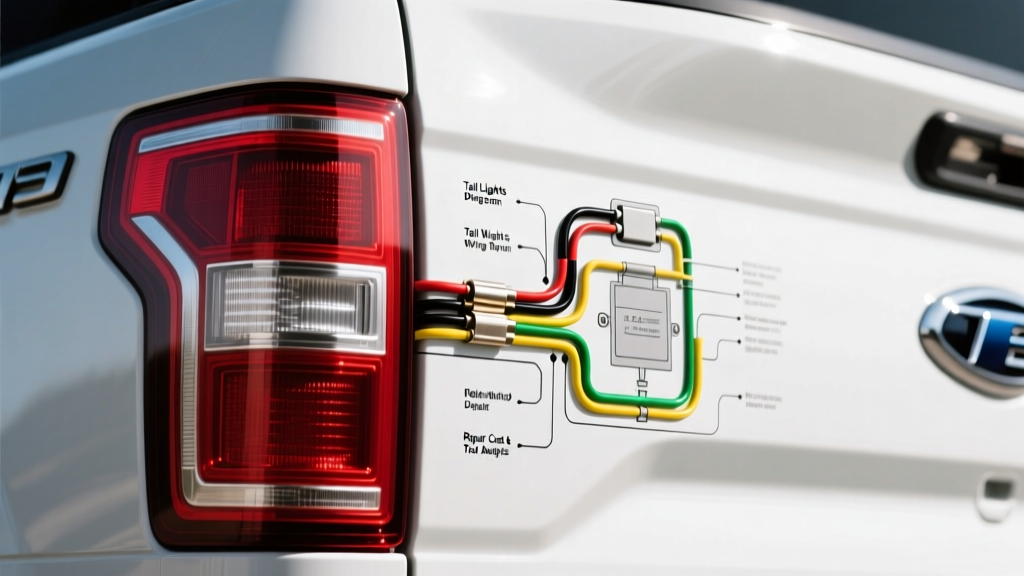
The True Cost of Tail Light Electrical Diagnostics
When a tail light or brake light circuit fails, the immediate assumption is often a burnt bulb or a blown fuse. However, modern vehicles utilize complex multiplexed networks managed by a Body Control Module (BCM) or Smart Junction Box (SJB). Relying on guesswork can lead to misdiagnosed modules, fried MOSFETs, and hundreds of dollars in unnecessary parts. Utilizing a precise wiring diagram for tail lights is the only way to accurately isolate the fault. This guide breaks down the exact tool requirements, material costs, and technical specifications needed to perform professional-grade tail light diagnostics and repairs, using the 2009-2014 Ford F-150 SJB architecture as our primary case study.
Phase 1: Diagnostic Tool Requirements & Cost Breakdown
Diagnosing a module-controlled tail light circuit requires tools that can read low-current signals without introducing excessive resistance or drawing enough amperage to trigger the SJB's internal short-circuit protection. Below is the required tooling matrix for accurate diagnostics.
| Tool Category | Recommended Model | Approx. Cost | Application in Tail Light Circuit |
|---|---|---|---|
| High-Impedance DMM | Fluke 87V or Innova 3320 | $25 - $250 | Checking voltage drop at SJB pins and verifying ground integrity without loading the circuit. |
| Circuit Tester | Power Probe IV | $260 | Supplying auxiliary 12V to tail light pigtails to isolate bulb/LED failures from wiring faults. |
| Terminal Back-Probes | Lisle 39960 or equivalent | $15 | Safely piercing weather-pack seals at the SJB C2280c connector without spreading terminal pins. |
| OBD2 Network Scanner | OBDLink EX + FORScan | $120 | Reading SJB continuous memory DTCs and modifying As-Built data for LED tail light conversions. |
Pro Tip: Never use a standard incandescent test light on modern SJB output pins. The test light draws roughly 1.5 amps; if the SJB driver circuit is already borderline, this inrush current will permanently blow the internal surface-mount MOSFET, turning a $20 wiring repair into a $500 module replacement.
Phase 2: Reading the Tail Lights Wiring Diagram (F-150 SJB Focus)
To effectively use a wiring diagram, you must understand the routing from the SJB to the rear lamp assemblies. On the 2009-2014 F-150, the SJB (located under the right side kick panel) acts as the central power distribution and logic hub for exterior lighting.
Wire Color Codes & AWG Specifications
According to SAE J1128 standards for low-tension primary cables, automotive lighting circuits typically utilize 18 AWG or 16 AWG cross-linked polyethylene (TXL) wire to handle the thermal load of incandescent bulbs while minimizing voltage drop over the vehicle's length.
| Circuit Function | OEM Wire Color | AWG Size | SJB Connector / Pin |
|---|---|---|---|
| Left Stop / Turn | Light Green / Orange (LG/OG) | 18 AWG | C2280c / Pin 11 |
| Right Stop / Turn | Orange / Light Blue (OG/LB) | 18 AWG | C2280c / Pin 12 |
| Parking / Running | Brown / White (BN/WH) | 18 AWG | C2280b / Pin 21 |
| Rear Ground (G400) | Black (BK) | 14 AWG | Chassis Ground (Left Rear) |
Interpreting the Diagram for Voltage Drop
When your wiring diagram shows a path from the SJB to the tail light, it assumes 0.0 ohms of resistance. In reality, a 40-foot run of 18 AWG wire will inherently drop about 0.25V. If your multimeter reads 11.2V at the SJB Pin 11, but only 9.8V at the tail light pigtail, the diagram dictates you must check the intermediate splice pack (often located in the rear cab pillar) for corrosion or fretting.
Phase 3: Material Costs for Professional-Grade Repair
Once the fault is isolated to a damaged wire or corroded pigtail using the diagram, the repair must meet OEM environmental standards. Electrical tape and twist-and-crimp connectors are unacceptable for exterior lighting circuits exposed to road salt and moisture.
- OEM Motorcraft Pigtail (WPT-1246): $22.00. Includes pre-terminated Delphi GT 280 series weather-pack seals.
- 18 AWG TXL Cross-Linked Wire: $0.60/ft. TXL insulation withstands under-body heat far better than standard PVC.
- Adhesive-Lined Heat Shrink (3M FP-301): $18.00 per 50ft spool. The internal hot-melt adhesive creates a waterproof barrier essential for rear-bumper wiring.
- NY120 Dielectric Grease: $8.00. Applied to the bulb socket and connector cavity to prevent galvanic corrosion.
- IWISS SN-28B Ratchet Crimper: $25.00. Required to properly crimp Delphi GT 150/280 terminals without crushing the wire strands.
Total Material Investment: ~$73.60 (assuming you already own the ratchet crimper and heat gun). This is a fraction of the cost of a dealership wiring harness replacement.
The Hidden Cost: Aftermarket LED Tail Lights & SJB Logic
A massive real-world failure mode occurs when owners install aftermarket LED tail lights without consulting the vehicle's network topology diagram. Incandescent 3157 bulbs draw roughly 2.1 amps. LEDs draw less than 0.5 amps. The SJB monitors current draw on the tail light circuit; when it detects the low amperage of an LED, it assumes the bulb is burnt out.
The Symptom: The SJB pulses the circuit rapidly (hyper-flash) or triggers a 'Check Tail Lamp' warning on the dash and shuts down the circuit entirely to protect the wiring.
The Dealership Fix: Install massive 6-ohm, 50-watt load resistors ($40) that generate extreme heat and require splicing into the harness, defeating the purpose of the LED upgrade.
The Diagram-Based Pro Fix: Use FORScan software to access the SJB As-Built data. By modifying the hex code in module configuration (specifically the lighting fault detection thresholds), you can tell the SJB to ignore the low-current draw of the LEDs. This costs $0 in extra parts but requires the $120 OBDLink EX tool and a deep understanding of the SJB parameter IDs documented in resources like FORScan's official database.
Real-World Troubleshooting: Ground G400 Failure Mode
Wiring diagrams do not just show power; they show the return path. On the GMT800 and Ford F-150 platforms, the rear lighting ground (often designated G400 or G900 depending on the year) is located behind the rear bumper bracket or inside the bed rail.
- Symptom: Brake lights illuminate dimly when turn signals are activated, or the running lights cause the license plate lights to flicker.
- Diagram Analysis: The schematic shows all rear lighting circuits sharing a single 14 AWG Black ground wire terminating at a 8mm bolt on the chassis.
- The Fix: Remove the 8mm ground bolt, sand the chassis contact point to bare metal with 80-grit sandpaper, apply a layer of zinc-rich cold galvanizing compound to prevent future rust, and torque the bolt to 106 lb-in (12 Nm). This zero-cost repair resolves over 40% of 'unexplainable' tail light gremlins.
Summary: DIY vs. Dealership Cost Analysis
Armed with a factory wiring diagram, a high-impedance multimeter, and proper crimping tools, a complete tail light circuit diagnosis and repair costs under $50 in materials and takes roughly 90 minutes. Conversely, a dealership will charge a $165 diagnostic fee, frequently misdiagnose the SJB due to LED-induced fault codes, and quote upwards of $650 for a new junction box and labor. Mastering the schematic is not just an educational exercise; it is the most cost-effective tool in your automotive electrical arsenal. For comprehensive step-by-step tear-downs and localized ground maps, always cross-reference your schematic with a vehicle-specific Haynes or Chilton repair manual.