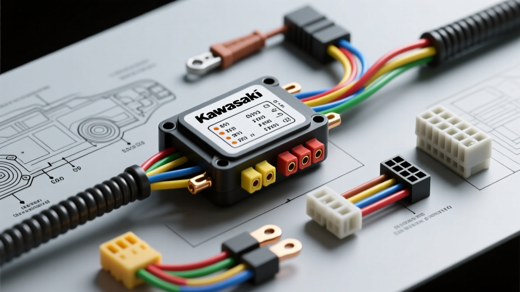
Understanding Kawasaki Transistorized Ignition Architecture
Modern Kawasaki motorcycles, ranging from the Ninja sportbike lineup to the Versys and KLR adventure platforms, utilize a fully transistorized, digitally mapped ignition system. Unlike older analog Capacitor Discharge Ignition (CDI) units that relied on simple capacitor dumping, modern Kawasaki igniters (often referred to as the ECU or Igniter unit) use sophisticated microprocessors to calculate inductive dwell time based on engine RPM, throttle position, and engine temperature. To properly diagnose a no-spark condition or perform a custom harness build, a thorough understanding of the Kawasaki ignition wiring diagram is mandatory. This technical specification reference breaks down the core circuit architecture, JIS (Japanese Industrial Standard) wire color codes, and precise multimeter testing procedures required for accurate diagnostics.
Core Ignition Circuit Architecture and Wire Standards
Kawasaki adheres strictly to JIS color coding for its electrical harnesses, which differs subtly from standard DIN or SAE color codes. The main battery feed to the ignition system typically utilizes a Red wire for constant 12V and a White/Red wire for switched 12V power originating from the main relay. Ground circuits are predominantly Black/Yellow or Black/White, depending on the specific sub-system. Signal wires from the stator pickup coils usually employ White/Red and White/Blue or Black/Red pairings.
Regarding wire gauge, the primary coil triggers and sensor signals use 18 AWG to 20 AWG stranded copper to maintain flexibility and reduce harness bulk. However, the main battery feeds and the primary power feeds to the ignition coils require 14 AWG or 16 AWG wire to prevent voltage drop under high-current dwell states. When repairing or extending these circuits, technicians should adhere to SAE J1128 standards for Low Tension Primary Cable, which dictate the insulation thickness and heat resistance required for engine-bay wiring. Using standard PVC wire instead of high-temperature TXL (cross-linked polyethylene) wire will lead to premature insulation meltdown near the exhaust headers and cylinder head.
Kawasaki Igniter Main Connector Pinout Reference
The heart of the Kawasaki ignition system is the Igniter module. While pinouts vary slightly between inline-four and parallel-twin engines, the fundamental logic remains consistent. Below is the standardized pinout reference for a typical 8-pin Kawasaki Igniter connector found on many 600cc to 900cc platforms.
| Pin | Function | Wire Color (JIS) | Wire Gauge | Circuit Description |
|---|---|---|---|---|
| 1 | Main Relay Power | White/Red | 16 AWG | Switched 12V power from the main ignition relay. |
| 2 | Chassis Ground | Black/Yellow | 16 AWG | Primary logic and power ground to the frame/battery. |
| 3 | Engine Stop (Kill) | Black/White | 18 AWG | Grounded by the kill switch to halt ignition spark. |
| 4 | Pickup Coil Signal (+) | White/Red | 20 AWG | Positive AC reference signal from the stator pulser. |
| 5 | Pickup Coil Signal (-) | Black/Red | 20 AWG | Negative/Reference ground for the stator pulser. |
| 6 | Bank Angle Sensor | Light Green/Black | 20 AWG | Receives 5V logic signal; cuts spark if bike tips over. |
| 7 | Ignition Coil 1 Trigger | Black/Yellow | 18 AWG | Switched ground path for Cylinder 1 primary coil. |
| 8 | Ignition Coil 2 Trigger | Black/White | 18 AWG | Switched ground path for Cylinder 2 primary coil. |
Pickup Coil (Pulser) Wiring and Stator Integration
The pickup coil, mounted on the stator assembly behind the flywheel, generates the critical AC reference signal that tells the igniter the exact position and rotational speed of the crankshaft. The flywheel features a raised reluctor tooth that passes the magnetic pickup coil, inducing a rapid voltage spike. Because this signal operates at high frequencies and low voltages, the wiring must be shielded or routed away from high-tension spark plug leads to prevent electromagnetic interference (EMI).
Pickup Coil Resistance and Air Gap Specifications
When diagnosing a no-spark condition, the pickup coil is the first component to test. Use a digital multimeter set to the 2k Ohm range. Disconnect the stator connector and measure across the pickup coil pins.
- Target Resistance: 360 Ω to 540 Ω at 68°F (20°C).
- Maximum Allowable Variance: ± 10% between cylinders on multi-pickup systems.
- Reluctor Air Gap: 0.016 in to 0.031 in (0.4 mm to 0.8 mm).
Real-World Failure Mode: A common failure on high-mileage Kawasaki engines is heat soak within the pickup coil winding. The coil may test within specification when cold, but as engine oil temperatures exceed 200°F, the internal copper windings expand and short out, dropping the resistance below 300 Ω. This results in an intermittent no-spark condition that only occurs when the engine is fully warmed up. Always test resistance both cold and immediately after a hot stall event.
Ignition Coil Primary and Secondary Circuit Specifications
Kawasaki utilizes either traditional dual-post ignition coils with high-tension leads or modern stick-coils (COP - Coil on Plug) that mount directly into the cylinder head. Regardless of the physical design, the internal transformer specifications remain tightly controlled.
| Circuit | Specification | Multimeter Setting | Failure Symptom |
|---|---|---|---|
| Primary Winding Resistance | 1.2 Ω to 1.8 Ω | 200 Ω Range | Weak spark, misfire under heavy load/high boost. |
| Secondary Winding Resistance | 12,500 Ω to 18,500 Ω | 20k Ω Range | Idle misfire, failure to fire across wide plug gaps. |
| Spark Plug Cap Resistance | 4,500 Ω to 5,500 Ω | 20k Ω Range | RF interference, ECU sensor ghosting, rough idle. |
The primary circuit relies on constant 12V power (White/Red) supplied to the positive terminal of the ignition coil. The negative terminal is connected to the Igniter via the Black/Yellow or Black/White trigger wire. The Igniter acts as a high-speed solid-state relay, sinking the primary coil to ground to build the magnetic field (dwell), and then abruptly opening the circuit to collapse the field and induce the high-voltage secondary spark.
Diagnostic Troubleshooting: Multimeter Testing Procedures
Effective troubleshooting of the Kawasaki ignition wiring diagram requires a systematic approach to isolate the fault to either the power supply, the trigger signal, or the high-tension output. As outlined in Electrosport Industries technical documentation on motorcycle ignition systems, verifying voltage integrity before condemning solid-state components is critical.
1. Verifying the Engine Stop (Kill) Circuit
The Engine Stop circuit (Pin 3, Black/White wire) is a normally-open switch that grounds the circuit when the rider presses the kill switch or turns the key to OFF. If the igniter detects a ground on this pin, it immediately ceases all primary coil switching. To test this circuit, set your multimeter to the continuity or resistance setting. Probe the Black/White wire at the igniter connector and a known good chassis ground. With the kill switch in the RUN position, the meter should read OL (Open Loop). With the switch in the OFF position, it should read near 0.0 Ω. If the circuit shows partial continuity (e.g., 45 Ω) in the RUN position, moisture or corrosion inside the right-hand switch housing is creating a voltage divider, confusing the igniter logic and causing a no-spark condition.
2. Testing the Pickup Coil Signal Output
While resistance testing confirms the coil is not broken, it does not confirm the coil is generating an adequate signal. To dynamically test the pickup coil, connect an AC Volts multimeter or, preferably, an automotive oscilloscope to the White/Red and Black/Red wires. Crank the engine using the starter motor. A standard multimeter will display an RMS AC voltage reading between 0.2V and 0.8V AC. An oscilloscope will reveal the true peak-to-peak voltage, which should spike above 2.0V to 4.0V as the reluctor tooth passes the sensor. If the voltage is present but the spark is missing, the fault lies within the Igniter module or the primary coil wiring.
3. Checking for Voltage Drop on the Main Power Feed
Solid-state igniters require a minimum of 10.5V to operate their internal logic gates and fire the ignition coils reliably. A weak battery or corroded main relay contacts can cause the voltage at the Igniter Pin 1 (White/Red) to drop below this threshold during cranking. Perform a voltage drop test by placing the positive multimeter lead on the battery positive post and the negative lead on the Igniter Pin 1 connector while an assistant cranks the engine. The voltage drop should not exceed 0.5V. If it reads 1.5V or higher, clean the main relay contacts, inspect the 30A main fuse block for heat deformation, and verify the integrity of the battery ground strap.
Connector Types and Harness Repair Best Practices
Kawasaki predominantly uses Sumitomo HM series and JST waterproof connectors for the ignition harness. These connectors feature silicone weather seals that prevent moisture intrusion into the terminal crimp zone. When depinning these connectors for repair, technicians must use the correct terminal extraction tool to depress the internal micro-lances without tearing the silicone seal. Attempting to pull the wire out with pliers will permanently ruin the connector housing.
When repairing a damaged ignition trigger wire, always use adhesive-lined heat shrink tubing and a ratcheting crimp tool. Soldering is generally discouraged in high-vibration engine harnesses because the solder wicks into the stranded wire, creating a rigid stress point that will eventually snap due to engine vibration. By strictly adhering to these wiring specifications and diagnostic procedures, technicians can accurately resolve complex Kawasaki ignition faults and ensure long-term harness reliability.