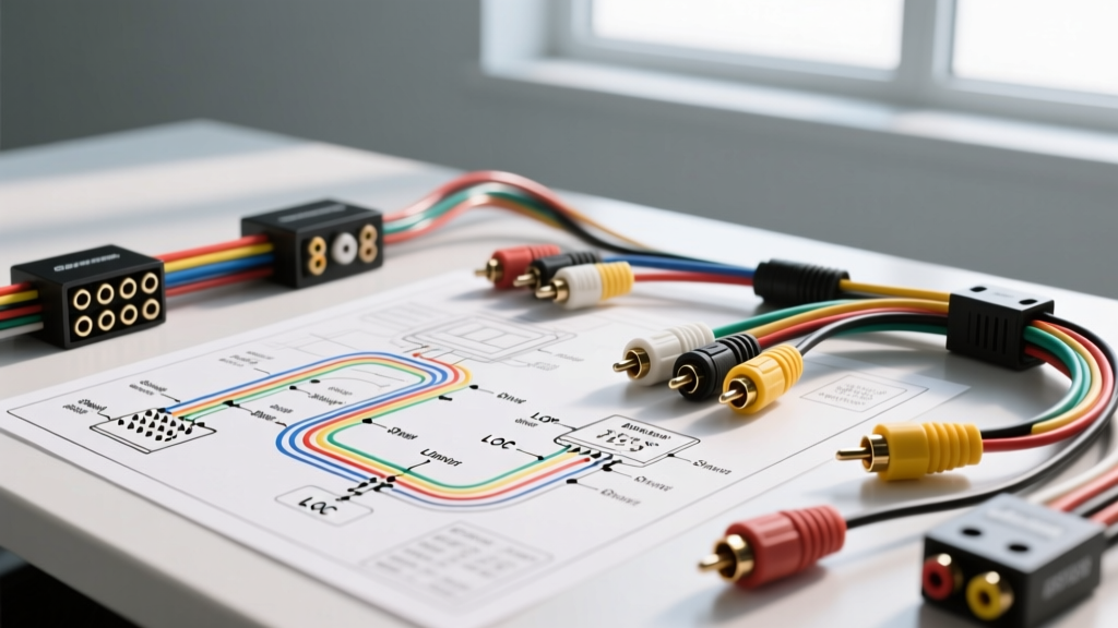
Introduction to Automotive Analog Signal Flow
When executing a high-fidelity car audio upgrade, transitioning from an OEM head unit to an aftermarket Digital Signal Processor (DSP) and multi-channel amplifiers requires a flawless analog signal path. The backbone of this signal path relies on RCA interconnects. However, unlike home theater environments, a vehicle is a hostile electrical ecosystem plagued by electromagnetic interference (EMI), alternator noise, and fluctuating ground potentials. Understanding the rca diagram of wiring for your specific DSP, Line Output Converter (LOC), and amplifiers is critical to achieving a noise-free, high-dynamic-range audio system.
This guide dives deep into the technical specifications, pinout configurations, and shielding physics required to properly wire RCA networks in modern vehicles, ensuring your upgrade project meets professional installation standards.
The Anatomy of Automotive RCA Cables
Before mapping out the signal flow, it is essential to understand the physical construction of the cables themselves. Automotive-grade RCA cables are unbalanced, coaxial interconnects designed to carry low-voltage analog audio signals (typically 2V to 5V RMS from an aftermarket head unit, or up to 8V+ from a high-end DSP).
- Center Conductor (Signal): Typically 24 AWG to 28 AWG stranded Oxygen-Free Copper (OFC) or silver-plated copper. This carries the positive audio signal.
- Dielectric Insulator: A polyethylene or Teflon layer separating the center conductor from the shield, dictating the cable's capacitance. Lower capacitance prevents high-frequency rolloff over long cable runs (e.g., from the dashboard to the trunk).
- Shield Braid (Ground): A woven copper or aluminum braid that serves two purposes: it acts as the signal return path (ground) and a Faraday cage to block EMI from the vehicle's alternator and ignition system.
- Outer Jacket: PVC or braided nylon to protect against abrasion, moisture, and automotive fluids.
The RCA Diagram of Wiring for Active LOC Integration
In modern vehicles equipped with premium OEM audio systems (such as Bose, Harman Kardon, or Mark Levinson), the factory amplifier outputs are often high-level, crossed-over, and EQ'd. To interface this with an aftermarket DSP, you must use an Active Line Output Converter (LOC) like the AudioControl LC2i or JL Audio CLEAN. The rca diagram of wiring for an active LOC involves both high-level speaker wire inputs and low-level RCA outputs, alongside a 12V remote turn-on circuit.
Active LOC Wiring Schematic
- High-Level Inputs: Splice into the OEM speaker wires (typically 18 AWG to 16 AWG). For example, in a Ford with a Sony DSP, the front left woofer signal might be White/Black (positive) and White (negative). Route these to the LOC's speaker-level terminal block.
- Power and Ground: Connect the LOC's +12V terminal to a clean, switched ignition source or the OEM amplifier's remote turn-on wire using 18 AWG primary wire. Ground the LOC to a bare metal chassis point using a ring terminal and a self-tapping screw, ensuring less than 0.1 ohms of resistance to the battery negative.
- RCA Outputs: Connect the LOC's male RCA outputs to the female RCA inputs of your DSP or amplifier. The shield of the RCA cable connects internally to the LOC's audio ground.
- AccuBASS / Load Resistors: If the OEM system uses Class-D amplifiers that require a minimum impedance load to prevent muting, integrate load resistors (typically 4-ohm, 10W) in parallel with the LOC's high-level inputs.
For detailed integration schematics, installers frequently refer to vehicle-specific wiring databases and Crutchfield's Car Audio Installation Guides to verify OEM wire colors and pinouts before tapping into the factory harness.
DSP Molex-to-RCA Breakout Harness Pinouts
Modern 8-channel and 12-channel DSPs (such as those from Helix, Audison, or JL Audio) rarely feature a dozen individual RCA jacks on the chassis. Instead, they utilize high-density Molex Mini-Fit Jr. or proprietary 18-pin to 22-pin connectors. A breakout harness translates these digital/analog pins into standard RCA pigtails.
Below is a reference table for a standard 16-pin DSP analog output breakout harness commonly used in European and American DSP architectures. Always consult your specific rca diagram of wiring manual, as pinouts vary by manufacturer.
| Molex Pin # | Wire Color (Breakout) | Signal Function | RCA Channel |
|---|---|---|---|
| 1 | White | Front Left (+) | CH 1 (FL) |
| 2 | White/Black | Front Left (-) | CH 1 Shield |
| 3 | Gray | Front Right (+) | CH 2 (FR) |
| 4 | Gray/Black | Front Right (-) | CH 2 Shield |
| 5 | Green | Rear Left (+) | CH 3 (RL) |
| 6 | Green/Black | Rear Left (-) | CH 3 Shield |
| 7 | Purple | Rear Right (+) | CH 4 (RR) |
| 8 | Purple/Black | Rear Right (-) | CH 4 Shield |
| 9 | Blue | Subwoofer 1 (+) | CH 5 (Sub 1) |
| 10 | Blue/Black | Subwoofer 1 (-) | CH 5 Shield |
| 11 | Brown | Subwoofer 2 (+) | CH 6 (Sub 2) |
| 12 | Brown/Black | Subwoofer 2 (-) | CH 6 Shield |
Note: The negative (-) wires in these breakout harnesses are not traditional speaker-level negatives; they are the shield/ground returns for the unbalanced RCA signal. They must be terminated to the outer shield barrel of the RCA plug.
Shield Grounding Physics and Alternator Whine Prevention
The most common failure in car audio modification projects is alternator whine—a high-pitched noise that rises and falls with engine RPM. This is caused by a ground loop. According to SAE International's J1113 standards on electromagnetic compatibility, vehicle chassis grounds are rarely at the exact same electrical potential due to the massive current draws of starters, AC compressors, and electric power steering systems.
The Golden Rule of RCA Shield Grounding
In an unbalanced RCA connection, the shield must be grounded at the source (the head unit, LOC, or DSP output) and remain floating (disconnected) at the destination (the amplifier input). If the shield is grounded at both ends, the voltage potential difference between the DSP's chassis ground and the Amplifier's chassis ground will force current to flow through the RCA shield. This current modulates the audio signal, injecting 60Hz to 120Hz alternator noise directly into your audio path.
Most high-quality aftermarket RCA cables and DSP breakout harnesses are internally wired to ground the shield at the source plug. If you are fabricating custom RCA cables using bulk coaxial wire and solderable RCA plugs (like Neutrik or Switchcraft), ensure the shield braid is soldered exclusively to the ground tab of the source-side RCA plug.
Routing, AWG, and EMI Best Practices
Proper routing is just as critical as the rca diagram of wiring itself. The low-voltage analog signal inside an RCA cable is highly susceptible to inductive coupling from high-current power wires.
- Separation Distance: Maintain a minimum separation of 12 inches between your RCA signal cables and your main power wires (typically 4 AWG to 1/0 AWG for high-output systems).
- The 90-Degree Rule: If RCA cables and power wires must cross, they must intersect at a strict 90-degree angle. Running them parallel, even for a few feet, creates an antenna effect that will induce EMI.
- Twisted Pair vs. Coaxial: While standard RCA is coaxial, some high-end DSPs offer balanced (differential) outputs using XLR or TRS connections, which utilize twisted-pair geometry to reject common-mode noise. If your DSP supports balanced outputs and your amplifiers accept them, use twisted-pair wiring instead of standard RCA to completely eliminate EMI susceptibility over long runs.
Troubleshooting RCA Signal Loss and Noise
When an audio system fails to produce sound or exhibits severe noise, use this diagnostic decision tree to isolate the RCA network:
- Symptom: Intermittent audio dropout on one channel.
- Cause: Broken center pin solder joint inside the RCA plug, or a fractured 24 AWG center conductor due to tight bending radii during installation.
- Fix: Use a digital multimeter (DMM) in continuity mode. Probe the center pin of the RCA plug and the corresponding Molex pin or LOC terminal. Replace the cable if resistance fluctuates when the cable is wiggled.
- Symptom: Severe alternator whine that scales with RPM.
- Cause: Ground loop (shield grounded at both ends) or RCA cables routed parallel to 0 AWG amplifier power wire.
- Fix: Verify amplifier and DSP share a common, heavy-gauge ground point. If the ground is solid, install a 1:1 ground loop isolator (audio transformer) on the RCA line, though this may slightly degrade the frequency response below 40Hz.
- Symptom: Hissing or white noise at high frequencies.
- Cause: DSP output voltage set too low, forcing the amplifier's gain (input sensitivity) to be cranked up, thereby amplifying the system's inherent noise floor.
- Fix: Use an oscilloscope or a true RMS AC voltmeter to set the DSP's RCA output voltage to the maximum unclipped level (usually 4V to 5V RMS), then lower the amplifier's gain to match. Refer to AudioControl's technical documentation on proper gain staging.
Conclusion
Executing a flawless car audio modification requires treating the analog signal path with the same respect as high-current power distribution. By mastering the rca diagram of wiring, adhering to strict shield-grounding protocols, and utilizing proper Molex breakout pinouts, you ensure that your DSP's processing power is delivered to your amplifiers with absolute transparency and zero noise.