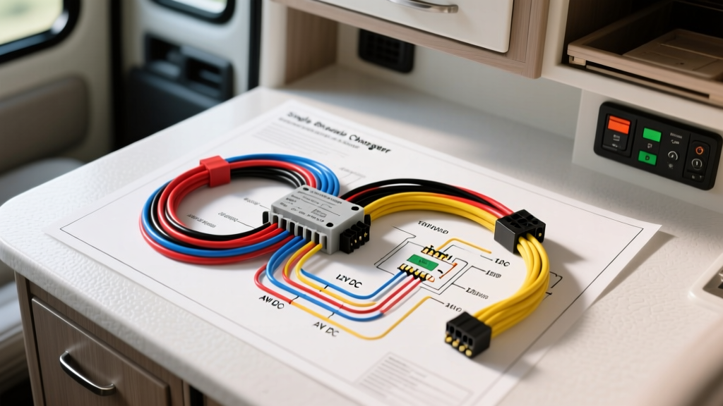
Bridging AC and DC: The Mobile Single Phase Changeover Switch
When automotive electrical engineers and RV technicians search for a single phase changeover switch wiring diagram PDF, they are typically met with residential standby generator schematics. However, integrating a 120V AC single-phase transfer switch into a Class A motorhome, mobile command center, or overland expedition vehicle requires a specialized dual-system approach. Unlike static home installations, vehicle-mounted changeover switches must seamlessly manage 120V AC shore power and onboard generator inputs while communicating with the vehicle’s 12V DC chassis network and generator Engine Control Unit (ECU).
This guide bridges the gap between standard AC electrical diagrams and heavy-duty automotive wiring standards. We will compare top-tier changeover products, decode the AC and DC wiring schematics, and provide exact AWG specifications, pinouts, and torque values required for a safe, NFPA-compliant mobile installation.
Product Comparison: Manual vs. Automatic Transfer Switches (ATS)
Selecting the correct changeover switch depends on your vehicle's power architecture and automation requirements. Manual rotary switches are robust and immune to control-circuit failures, while Automatic Transfer Switches (ATS) rely on 12V DC relay coils to prevent hot-plugging and manage neutral bonding automatically.
| Feature | Go Power! TS-30 (Manual) | IOTA ATS-501 (Automatic) | Progressive Dynamics PDATS (Auto) |
|---|---|---|---|
| Amperage Rating | 30A / 120V Single Phase | 50A / 120V Single Phase | 50A / 120V Single Phase |
| Switching Mechanism | Rotary Cam Switch | Double-Throw Electromechanical Relays | Solid-State Contactor Hybrid |
| DC Control Integration | None (Manual Operation) | 12V DC Coil Trigger via Gen ECU | 12V DC Coil + Microprocessor Logic |
| Transfer Time | Manual (Break-Before-Make) | < 250ms (Grid-Grade) | < 150ms with Voltage Sensing |
| Neutral Bonding | Switched Neutral Required | Internal Gen Neutral Bond Relay | Programmable Neutral Bond Relay |
Decoding the Single Phase Changeover Switch Wiring Diagram PDF
A standard mobile single-phase changeover schematic is divided into two distinct circuits: the high-voltage AC power routing and the low-voltage DC control logic. Understanding both is critical for Class A motorhome chassis integration (e.g., Freightliner XCS or Spartan Mountain Master platforms).
1. AC Power Routing (120V Single Phase)
The AC side of the diagram handles the physical transfer of the 120V load. In a 50A RV system, you are technically dealing with two 120V legs (L1 and L2) derived from a split-phase 240V source, but the changeover switch treats each leg as an independent single-phase circuit.
- Source 1 (Shore Power): Routed from the exterior 50A twist-lock inlet (L14-50R) to the ATS 'LINE 1' terminals.
- Source 2 (Generator): Hardwired directly from the onboard generator (e.g., Cummins Onan RV QD 12000) output junction box to the ATS 'LINE 2' terminals.
- Load (Main Distribution Panel): The ATS 'LOAD' terminals feed the RV's AC breaker panel.
- Grounding Continuity: The Equipment Grounding Conductor (EGC) must remain continuous and unswitched. Green bonding screws inside the ATS must be removed if the main panel already bonds Neutral and Ground.
2. 12V DC Control Circuit Integration (The Automotive Side)
This is where the residential PDF diagrams fail and automotive expertise is required. An ATS must know when the generator is running to engage the transfer relays and activate the internal neutral-bonding relay. This requires tapping into the generator's ECU using automotive-grade wiring.
Most modern RV generators utilize a Deutsch DT series 4-pin connector for external control. The ATS controller interfaces with this ECU using the following pinout:
- Pin 1 (B+): 12V+ constant battery feed. Triggers the ATS microprocessor.
- Pin 2 (B-): Chassis ground. Must be bonded to the vehicle frame, not just the AC ground bus.
- Pin 3 (Start/Stop): Momentary 12V signal from the RV dash switch to crank the generator.
- Pin 4 (Run/Fault Status): 12V+ output from the ECU when the engine is actively running. This wire connects directly to the ATS 'Generator Present' logic coil.
Wire Gauge, Color Codes, and Connector Specifications
Adhering to SAE J1128 standards for low-tension primary cable and NFPA 1192 for RV AC wiring is mandatory to prevent voltage drop, relay chatter, and fire hazards.
| Circuit Function | Wire Type | AWG Size | Color Code | Terminal Torque Spec |
|---|---|---|---|---|
| AC Shore Power (L1/L2) | THHN/MTW Stranded | 6 AWG (50A) / 10 AWG (30A) | Black (L1), Red (L2) | 45 in-lbs (5.1 Nm) |
| AC Neutral | THHN/MTW Stranded | 6 AWG / 10 AWG | White | 45 in-lbs (5.1 Nm) |
| AC Equipment Ground | THHN/MTW Stranded | 10 AWG (Minimum) | Green / Bare Copper | 35 in-lbs (4.0 Nm) |
| DC Control B+ / B- | SAE J1128 GXL | 12 AWG | Red (+), Black (-) | 25 in-lbs (2.8 Nm) |
| DC ECU Run Signal | SAE J1128 GXL | 18 AWG | Blue | Pin Crimp (Deutsch DT) |
Real-World Troubleshooting: ATS Failure Modes in Motorhomes
When a mobile single-phase changeover switch fails, it rarely manifests as a simple 'no power' issue. Because the system bridges AC and DC environments, troubleshooting requires a systematic decision tree.
Symptom: ATS Chatter (Rapid Clicking) When on Generator Power
- Cause: Voltage drop on the 12V DC control wire (Pin 4) from the generator ECU to the ATS logic board. The ATS microprocessor sees the voltage dip below 9V and resets repeatedly.
- Fix: Upgrade the ECU Run Signal wire from 18 AWG to 14 AWG GXL. Ensure the ATS ground is tied directly to the chassis frame rail with a star washer, bypassing any painted surfaces.
Symptom: GFCI Outlets Trip Immediately on Generator Power, but Work on Shore Power
- Cause: Improper Neutral Bonding. Per RVIA and NFPA 1192 guidelines, the generator's neutral must be bonded to ground at the generator or inside the ATS, but never at the main distribution panel when on generator power. If the ATS internal bonding relay is stuck open, the GFCI will detect an imbalance and trip.
- Fix: Test the ATS internal neutral-bonding relay coil for 12V DC continuity. If the relay is functional, verify that the main AC panel's neutral bus bar is isolated from the ground bus bar.
Symptom: Shore Power Works, but ATS Will Not Transfer to Generator
Authoritative References & Further Reading
For complete schematic PDFs and code compliance, always consult the foundational standards governing mobile electrical systems:
- NFPA 1192: Standard on Recreational Vehicles - Mandates neutral bonding locations and AC wire routing separation from DC chassis harnesses.
- SAE J1128: Low Tension Primary Cable - Specifies the thermal and abrasion resistance requirements for the 12V DC control wires routed near the generator exhaust and engine bay.
- RVDA / RVIA Technical Bulletins - Provides updated service bulletins on ATS relay failures and shore power inlet torque specifications.
By treating the single-phase changeover switch not just as an AC component, but as a critical node in the vehicle's broader DC-to-AC electrical architecture, technicians can ensure reliable, safe power delivery in the most demanding expedition environments.