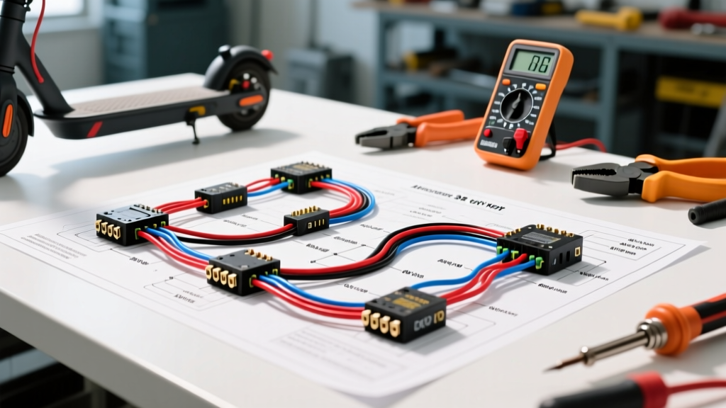
Executing the 36 Volt Electric Scooter Wiring Diagram PDF: A Cost and Tool Analysis
Locating an accurate 36 volt electric scooter wiring diagram pdf is only the first step in diagnosing, repairing, or upgrading a personal electric vehicle (PEV). Whether you are working on a generic Chinese brushless DC (BLDC) kick scooter, a heavy-duty mobility scooter, or a custom DIY build, interpreting the schematic requires a specific set of diagnostic tools and a clear understanding of material costs. A 36V system is not a single fixed voltage; it varies wildly based on battery chemistry. A 36V lead-acid system (three 12V cells in series) operates between 31.5V (depleted) and 38.2V (charging). Conversely, a 36V Lithium-Ion system (10S configuration) operates between 30.0V and 42.0V. This 4-volt differential at the top end can easily fry undersized signal wires or cause thermal runaway if the wiring harness is not built to SAE J1128 Low Tension Primary Cable standards.
This comprehensive cost and tool requirements analysis breaks down exactly what you need to safely execute a 36V scooter wiring diagram, from precision crimping tools to the hidden costs of replacing melted bulkhead connectors. We will also decode standard BLDC controller pinouts so you can map your PDF schematic to the physical wires on your workbench.
Essential Tool Requirements for 36V Scooter Electrical Work
Working with 36V DC systems (which can push 20 to 30 amps continuous, and up to 50 amps peak) requires tools that ensure low-resistance connections. High resistance at a crimp joint generates heat, which melts insulation and causes voltage drops that mimic a failing battery or controller.
Diagnostic and Testing Equipment
- True-RMS Digital Multimeter (DMM): You need a DMM capable of measuring DC voltage up to 60V and DC current up to 20A. A standard automotive meter might suffice, but for reading the 0.8V to 4.2V throttle signal and the 5V Hall sensor square waves, a fast-sampling True-RMS meter is mandatory.
- Inductive Clamp Meter: Essential for measuring phase wire current (AC PWM) without piercing the 14 AWG silicone insulation. Piercing phase wires introduces moisture pathways that lead to copper oxidation and eventual phase-to-phase shorts.
- Electronic Load Tester: To verify if the 36V battery pack is experiencing voltage sag under load, which often tricks riders into thinking their wiring or controller is faulty.
Termination and Crimping Tools
The most common failure point in any 36 volt electric scooter wiring diagram pdf implementation is the signal connector. Most scooters use JST-SM or Molex connectors for Hall sensors and throttles. Using generic, non-ratcheting pliers to crimp JST-SM pins results in deformed tabs that fail to lock into the nylon housing, leading to intermittent 5V Hall signal drops. According to the IPC/WHMA-A-620 standard for cable and wire harness assemblies, a proper crimp must exhibit a specific compression ratio without cutting into the wire strands. You must invest in a ratcheting crimper specifically calibrated for 2.54mm pitch JST-SM terminals (such as the SN-28B or IWISS IWS-3220M). For the main power lines, a heavy-duty hexagonal crimp die is required for 10 AWG and 12 AWG ring terminals and XT60 bullet connectors.
Material Cost Breakdown: Rewiring a 36V BLDC System
Budgeting for a full harness rebuild or a controller swap requires understanding the difference between cheap PVC wire and high-strand-count silicone wire. PVC wire stiffens, cracks, and melts under the high-amperage heat generated by 36V scooter motors. High-temperature silicone wire (rated for 200°C) is mandatory for the battery-to-controller and controller-to-motor runs.
| Component / Material | Specification | Est. Cost (USD) | Technical Notes |
|---|---|---|---|
| Main Power Wire | 12 AWG Silicone (Red/Black) | $18.00 | Handles 30A continuous; 600V insulation rating. |
| Motor Phase Wire | 14 AWG Silicone (Y/G/B) | $14.00 | Must match controller phase output terminals. |
| Signal / Sensor Wire | 22 AWG Stranded (Multi) | $9.00 | Used for Throttle, Hall Sensors, and Brakes. |
| 36V BLDC Controller | 25A Cont. / 50A Peak | $45.00 - $85.00 | Must support 10S Li-Ion LVC (Low Voltage Cutoff) at 30V. |
| Connectors (Power) | XT60 / AS150 (Male/Female) | $8.00 | AS150 recommended for peak draws over 40A. |
| Connectors (Signal) | JST-SM 2/3/5 Pin Kits | $12.00 | Includes pre-insulated crimp terminals and nylon housings. |
| Adhesive Heat Shrink | 3:1 Ratio with Sealant | $10.00 | Waterproofs XT60 solder joints against road spray. |
Total Estimated DIY Material Cost: $116.00 - $156.00. Professional shops typically charge $85 to $150 per hour for labor, making the DIY approach highly cost-effective if you possess the correct crimping and soldering tools.
Technical Deep Dive: 36V Controller Pinout and Wire Color Codes
Most generic 36V scooter wiring diagrams use a standardized color code for BLDC controllers. However, always verify with your multimeter before plugging in the battery, as some manufacturers swap the Red and Black wires on the 3-pin throttle connector, which will instantly destroy the 5V voltage regulator inside the controller.
| Function | Standard Wire Color | AWG Size | Connector Type | Voltage / Signal Profile |
|---|---|---|---|---|
| Main Battery (+) | Red | 12 AWG | XT60 / Ring Terminal | 30.0V - 42.0V DC |
| Main Battery (-) | Black | 12 AWG | XT60 / Ring Terminal | Ground (0V) |
| Motor Phase A | Yellow | 14 AWG | 4mm Bullet | 3-Phase AC PWM |
| Motor Phase B | Green | 14 AWG | 4mm Bullet | 3-Phase AC PWM |
| Motor Phase C | Blue | 14 AWG | 4mm Bullet | 3-Phase AC PWM |
| Hall Sensor VCC | Red | 22 AWG | JST-SM 5-Pin | 5.0V DC Regulated |
| Hall Sensor GND | Black | 22 AWG | JST-SM 5-Pin | 0V |
| Hall A / B / C | Yellow / Green / Blue | 22 AWG | JST-SM 5-Pin | 0V - 5V Square Wave |
| Throttle VCC | Red | 22 AWG | JST-SM 3-Pin | 5.0V DC |
| Throttle Signal | Green or White | 22 AWG | JST-SM 3-Pin | 0.8V (Idle) to 4.2V (Full) |
Hidden Costs and Troubleshooting Common 36V Failures
When following a 36 volt electric scooter wiring diagram pdf, technicians often encounter "ghost" faults that are not explicitly detailed in the schematic. The most common hidden cost in 36V repairs is the degradation of the battery management system (BMS) discharge MOSFETs. If your multimeter reads 42V at the battery terminals, but the voltage drops to 28V the moment you engage the throttle, the wiring harness is likely fine. The BMS is tripping its over-current protection due to degraded internal cells or a failing MOSFET. Replacing a 10S 30A BMS adds roughly $25 to $40 to your project cost.
Diagnostic Decision Tree: Motor Stuttering and Hall Sensor Faults
If your scooter motor stutters, vibrates loudly, or refuses to spin after a wiring repair, follow this diagnostic path before replacing the controller:
- Check Phase Wire Continuity: Disconnect the battery. Use the DMM continuity setting to test from the controller side of the XT60 to the motor bullet connectors. Ensure Yellow maps to Yellow, Green to Green, and Blue to Blue. A swapped phase wire will cause the motor to lock up and draw massive current, potentially melting the 14 AWG wire.
- Verify 5V Hall Power: Reconnect the battery. Back-probe the 5-Pin JST-SM Hall connector at the controller end. Pin 1 (Red) must read exactly 5.0V. If it reads 0V, the controller's internal 7805 voltage regulator is blown (requires controller replacement, ~$50).
- Test Hall Signal Output: Jack up the rear wheel. Set the DMM to DC Voltage. Back-probe the Yellow, Green, and Blue Hall signal wires while slowly spinning the wheel by hand. The voltage on each wire should toggle cleanly between 0.0V and 5.0V. If one wire stays stuck at 0V or 5V, the internal Hall sensor inside the motor hub has failed, requiring a motor teardown or a sensorless controller upgrade.
Authoritative References and Safety Standards
When designing or repairing high-current DC harnesses, adhering to established electrical standards prevents catastrophic thermal events. For comprehensive data on wire insulation ratings, ampacity charts, and temperature derating, refer to the SAE J1128 Low Tension Primary Cable specifications. Furthermore, understanding the charging and discharging profiles of 10S Lithium-Ion packs is critical for setting the correct Low Voltage Cutoff (LVC) on your 36V controller. Premature cutoff reduces range, while late cutoff destroys the battery chemistry. Detailed parameters for Li-Ion voltage curves and BMS configurations can be found via Battery University's technical archives. Finally, ensure all signal and power crimps meet the mechanical and electrical pull-test requirements outlined in the IPC/WHMA-A-620 standard to guarantee long-term reliability against the heavy vibrations inherent to electric scooter operation.