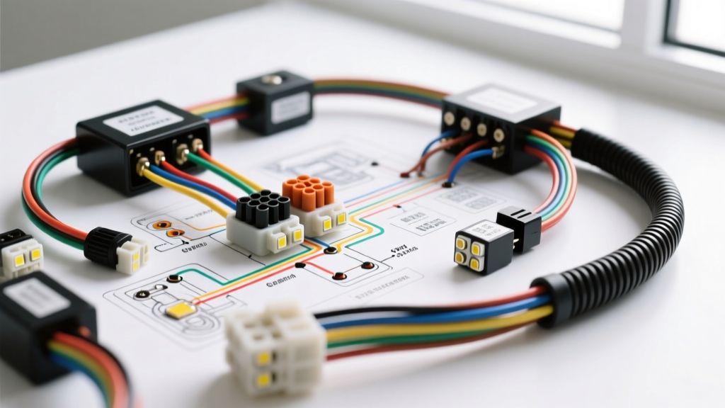
Understanding the Standard 12V LED Relay Architecture
When consulting an LED wiring diagram, 12V automotive circuits typically rely on a standard 4-pin ISO mini relay to isolate high-amperage loads from delicate cabin switches. Whether you are troubleshooting an aftermarket LED light bar on a Jeep Wrangler, a roof rack array on a Toyota Tacoma, or auxiliary pods on a Ford F-150, the fundamental electrical architecture remains identical. Failure to diagnose these circuits systematically leads to misdiagnosed components, melted wire looms, and parasitic draws.
According to SAE J1128 standards for low-tension primary cable, wire gauge selection and insulation temperature ratings are critical in high-underhood-temperature environments. Before initiating the troubleshooting flow, verify your physical wiring matches the industry-standard 4-pin relay pinout detailed below.
Standard 4-Pin Relay Pinout & Harness Specifications
| Relay Pin | Function | Typical Wire Color | Min. AWG Size | Connector Interface |
|---|---|---|---|---|
| 30 | 12V+ Battery Feed (Fused) | Red | 10 AWG | 5/16' Ring Terminal |
| 87 | Load Output (LED +) | Yellow or White | 10 AWG | Deutsch DT (Pin 1) |
| 86 | 12V+ Trigger (Switch) | Blue | 14 AWG | Metri-Pack 280 / Spade |
| 85 | Ground (-) | Black | 14 AWG | 1/4' Ring Terminal |
Step-by-Step Troubleshooting Flow for 12V LED Circuits
Use a Digital Multimeter (DMM) with high-impedance inputs and a set of back-probe pins to execute the following diagnostic decision tree. Never pierce wire insulation with test lights, as this introduces moisture ingress and future corrosion points.
Symptom 1: Complete Failure (No Light, No Relay Click)
If the LED array remains dark and you do not hear the distinct mechanical click of the relay coil engaging, the fault lies in the low-current trigger circuit (Pins 85 and 86).
- Verify Trigger Voltage: Set your DMM to DC Volts. Back-probe Pin 86 at the relay socket while activating the cabin switch. You should read battery voltage (12.2V - 12.6V). If 0V, trace the 14 AWG blue wire back to the switch for an open circuit or blown dash fuse.
- Test the Ground Path: Move the DMM black lead to the battery positive terminal and the red lead to Pin 85. If you read 12V+, the ground path is intact. If 0V, the black ground wire is severed or the ring terminal is corroded at the chassis grounding point.
- Inspect the Switch: Many aftermarket rocker switches feature internal LED illumination. If the switch's internal LED is dead, the switch itself has failed or lacks primary 12V feed and ground on its secondary illumination pins.
Symptom 2: Relay Clicks, but LEDs Remain Dark
A clicking relay confirms the coil circuit (Pins 85/86) is functional. The fault is now isolated to the high-current load circuit (Pins 30 and 87).
- Check Constant Power: Probe Pin 30 at the harness plug. It must show constant 12V+ regardless of the ignition or switch position. If dead, check the inline Maxi-fuse or AGU fuse holder near the battery positive terminal.
- Perform a Voltage Drop Test on the Load Side: Connect the DMM red lead to Pin 87 and the black lead to the battery negative terminal. Activate the switch. You should read within 0.2V of the battery's resting voltage. A reading of 8V or lower indicates severe resistance in the 10 AWG yellow wire or a corroded Metri-Pack 280 terminal inside the relay socket.
- Inspect the Deutsch DT Connector: Off-road LED bars utilize 2-pin or 3-pin Deutsch DT connectors. Unplug the connector and inspect the silicone seals. If water has bypassed the wedge lock, the copper crimps will exhibit green/white copper oxide corrosion, creating an open circuit.
Symptom 3: Flickering, Dimming, or 'Ghost' Illumination
Flickering under high RPM or dimming at idle indicates a voltage drop issue, poor grounding, or interference from the vehicle's charging system.
- Measure Ground Voltage Drop: Place the DMM red lead on the battery negative terminal and the black lead on the LED light bar's aluminum housing (or the ground wire pin). Turn the lights on. A voltage drop greater than 0.1V indicates a poor chassis ground. Remove the ground ring terminal, sand the chassis to bare metal with 80-grit sandpaper, apply dielectric grease, and torque the M6 or M8 bolt to 10-15 lb-ft.
- Check for Alternator Whine/AC Ripple: Switch the DMM to AC Volts and measure across the battery terminals with the engine running. If AC voltage exceeds 0.05V (50mV), your alternator diode pack is failing, injecting AC ripple into the DC system, which causes sensitive LED drivers to flicker.
Symptom 4: Inline Fuse Blows Instantly Upon Switching
An immediately blown fuse indicates a dead short to ground on the high-current side of the relay.
- Isolate the Light Bar: Unplug the Deutsch DT connector at the light bar. Replace the fuse and activate the switch. If the fuse holds, the short is internal to the LED bar's DC-DC driver board or the wiring harness has been pinched against a sharp metal edge near the grille.
- Inspect the Relay Socket: If the fuse blows with the light bar unplugged, the short is between Pin 87 and Pin 85 (ground) inside the relay harness. This frequently occurs when aftermarket harness manufacturers use substandard heat shrink, allowing the 10 AWG load wire to melt into the 14 AWG ground wire near the relay spades.
AWG Sizing and Voltage Drop Calculations
Undersized wiring is the leading cause of premature LED driver failure. LED drivers require a minimum input voltage (usually 9V-10V) to regulate current properly. Excessive voltage drop caused by thin wires forces the driver to pull higher amperage to compensate for the missing wattage, leading to thermal runaway. Reference Painless Performance automotive wiring guidelines for proper chassis routing.
Wire Gauge vs. Amperage for 12V LED Arrays
| Total LED Wattage | Approx. Amperage (at 12V) | Required Wire Gauge (Up to 15ft) | Inline Fuse Rating |
|---|---|---|---|
| Up to 60W | 5A | 16 AWG | 10A |
| 60W - 120W | 5A - 10A | 14 AWG | 15A |
| 120W - 240W | 10A - 20A | 10 AWG | 25A |
| 240W - 360W+ | 20A - 30A+ | 8 AWG | 40A |
Modern Vehicle CAN-Bus and PWM Interference
If you are installing an LED wiring diagram 12V setup in a late-model truck (e.g., 2015+ Ford F-150, 2019+ Ram 1500, or 2020+ Toyota Tacoma), you must account for Pulse Width Modulation (PWM) and CAN-Bus monitoring. Modern OEM upfitter switches and trailer lighting modules do not output a solid 12V+ DC signal. Instead, they output a PWM square wave to monitor circuit health and detect blown incandescent bulbs.
The Symptom: The LED light bar strobes rapidly, flashes intermittently, or the truck's dashboard displays a 'Trailer Wiring Fault' or 'Upfitter Circuit Overload' message.
The Fix: You must install a 12V DC filter capacitor or a dedicated PWM anti-flicker module inline on the trigger wire (Pin 86) between the OEM switch and the relay. This module absorbs the PWM square wave and outputs a clean, solid 12V+ DC signal to the relay coil, satisfying the vehicle's Body Control Module (BCM) while properly engaging the ISO relay. For detailed OEM pinouts and BCM integration, consult Hella's automotive relay and electronics technical documentation to ensure your relay coil resistance (typically 70-90 Ohms) matches the BCM's expected load parameters.
Summary of Best Practices
Successful 12V LED integration requires more than just connecting wires; it demands an understanding of voltage drop, relay coil isolation, and modern vehicle network interference. Always use adhesive-lined marine-grade heat shrink for all crimps, apply dielectric grease to all Deutsch and Metri-Pack connectors, and verify your ground points are secured to bare, unpainted chassis metal. By following this step-by-step troubleshooting flow, you can isolate electrical faults efficiently and ensure your auxiliary lighting operates reliably in the harshest automotive environments.