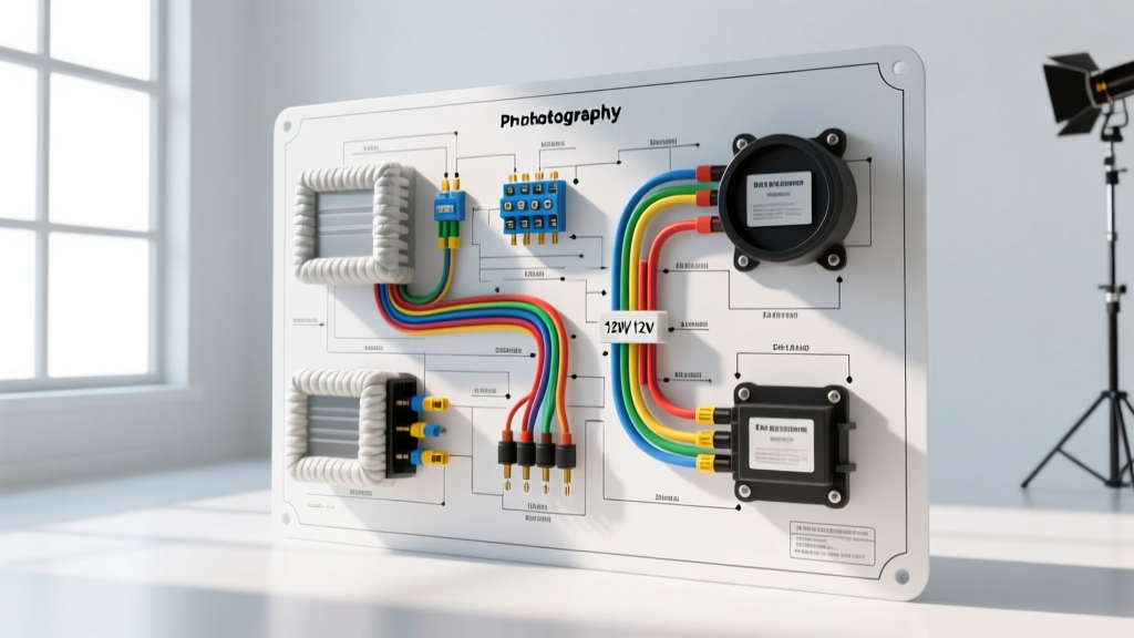
Introduction to RV Appliance Electrical Integration
Upgrading a Class A, Class C, or fifth-wheel motorhome with a ventless washer-dryer combo is one of the most popular boondocking modifications. However, integrating these high-draw appliances requires a meticulous approach to both 120V AC and 12V DC electrical systems. When consulting the OEM wiring diagram for dryer and washer combo units (such as the popular Splendide WD2100XC or LG ventless models), technicians must account for continuous amperage loads, voltage drop over long wire runs, and the harsh, high-vibration environment of a moving vehicle.
This comprehensive guide breaks down the exact tool requirements, material costs, and technical specifications needed to safely wire an RV washer-dryer combo. Whether you are a DIY RVer or a professional mobile technician, understanding the cost-to-benefit ratio of premium marine-grade wiring versus standard residential hardware is critical for long-term reliability.
Essential Tools & Upfront Cost Analysis
Automotive and RV electrical systems demand specialized tools to ensure gas-tight crimps and accurate diagnostics. Using residential-grade tools on mobile 120V/12V systems is a leading cause of thermal runaway and electrical fires. Below is the required tooling matrix and associated cost analysis for a professional-grade installation.
| Tool / Equipment | Specific Model Recommendation | Estimated Cost | Purpose in Dryer Wiring |
|---|---|---|---|
| True-RMS Multimeter | Fluke 117 or Klein Tools MM700 | $160 - $200 | Verifying 120V AC line voltage and 12V DC control logic under load. |
| Ratcheting Crimper | Ancor Marine Grade 12-10 AWG | $85 - $110 | Creating gas-tight, waterproof crimps on heat-shrink ring terminals. |
| Wire Stripper | Knipex ErgoStrip 16 95 | $45 - $60 | Stranding 10 AWG THHN without nicking the copper core. |
| Torque Screwdriver | CDI 401SM (10-50 in-lbs) | $130 - $150 | Torquing breaker lugs to 20 in-lbs to prevent arcing. |
| Thermal Camera | FLIR ONE Pro or Seek Thermal | $200 - $250 | Post-installation load testing to detect hot spots at bus bars. |
Total Professional Tool Investment: $620 - $770. For DIYers, borrowing or renting a torque screwdriver and thermal camera can reduce this initial capital expenditure by nearly 50%.
Decoding the Wiring Diagram for Dryer Combos
Locating an accurate wiring diagram for dryer and washer combos reveals two distinct electrical circuits: the high-amperage 120V AC heating/motor circuit, and the low-amperage 12V DC control/water pump circuit. Failing to isolate and properly size these circuits leads to nuisance tripping and potential wire meltdowns.
120V AC Main Power Circuit (The Heavy Lifting)
The heating element and drum motor on a standard RV combo unit require a dedicated 20A or 30A 120V AC circuit. According to the NFPA 1192 Standard on Recreational Vehicles, all branch circuits must be protected by appropriately sized overcurrent devices and utilize stranded copper wire to withstand vehicular vibration.
- Wire Gauge: 10 AWG Stranded Copper (THHN/THWN-2). Never use solid-core Romex in an RV; vibration will cause the solid copper to work-harden, snap, and arc.
- Wire Colors: Black (Hot), White (Neutral), Green or Bare (Chassis Ground).
- Breaker Sizing: 20A Dual-Pole or Single-Pole GFCI breaker (depending on the specific OEM schematic and proximity to water sources).
- Termination: #10 AWG heat-shrink ring terminals, crimped and torqued to 20 in-lbs at the breaker bus bar.
12V DC Control & Water Pump Integration
Many ventless combo units utilize a 12V DC solenoid to control internal water valves or to trigger the RV's onboard 12V water pump when the machine calls for water. The wiring diagram for dryer control boards typically shows a 12V input requiring a dedicated fused circuit.
- Wire Gauge: 12 AWG Stranded Marine-Grade Tinned Copper.
- Wire Colors: Red (12V+), White or Black (12V- / Ground).
- Overcurrent Protection: 15A ATO/ATC blade fuse located within 18 inches of the positive battery bus bar.
- Relay Integration: If the combo unit draws more than 5A on the 12V trigger circuit, a 30A Bosch-style automotive relay must be wired to handle the water pump load, protecting the delicate appliance control board from back-EMF voltage spikes.
Material Cost Breakdown & Voltage Drop Math
Budgeting for the raw materials is a critical phase of the cost analysis. Premium marine-grade materials cost approximately 30-40% more than standard automotive or residential hardware but offer superior corrosion resistance and vibration tolerance.
| Material Component | Specification | Estimated Cost |
|---|---|---|
| 10 AWG Stranded Wire | $1.20 / ft (x 50 ft run) | $60.00 |
| 12 AWG Tinned Wire | $0.85 / ft (x 30 ft run) | $25.50 |
| 20A GFCI Breaker | Square D or Siemens RV Rated | $45.00 |
| Heat Shrink Terminals | Ancor #10 Ring (Pack of 50) | $22.00 |
| Split Loom & Cable Ties | 1/2" Nylon Loom + UV Ties | $18.00 |
| Total Estimated Material Cost | $170.50 | |
The Voltage Drop Factor
In motorhomes, the distance from the main inverter/charger panel to the rear-mounted washer-dryer closet can easily exceed 40 feet (80 feet round-trip). The RV Industry Association (RVIA) recommends keeping voltage drop below 3% for critical appliances. Using the standard voltage drop formula: VD = (2 x K x I x L) / CM (where K=12.9 for copper, I=16A continuous draw, L=80ft, CM=10380 for 10 AWG), the voltage drop calculates to approximately 3.18V (2.6%). Upgrading to 8 AWG wire for runs exceeding 45 feet will drop this to a safer 1.6%, though it increases material costs by roughly $45.
Step-by-Step Termination & Routing Protocols
- Disconnect All Power: Shut off the main shore power, disconnect the inverter/charger, and pull the main 12V DC battery disconnect. Verify zero voltage with a True-RMS multimeter.
- Route the 120V AC Harness: Pull the 10 AWG 3-conductor cable through existing wire chases. Maintain a minimum 2-inch separation from 12V DC wiring and coaxial/data cables to prevent electromagnetic interference (EMI).
- Crimp and Seal: Strip 3/8" of insulation. Insert into the #10 heat-shrink ring terminal. Use the ratcheting crimper until the tool releases. Apply heat with a heat gun until the adhesive sealant oozes from the edges, creating a waterproof barrier against RV humidity.
- Terminate at the Breaker Panel: Land the Black wire on the 20A breaker, White on the neutral bus, and Green on the isolated ground bus. Torque the breaker set-screw to exactly 20 in-lbs. Under-torquing causes arcing; over-torquing strips the aluminum bus threads.
- Wire the 12V DC Logic: Connect the 12 AWG Red wire to a fused 12V distribution block. If integrating a water pump relay, wire the appliance's 12V trigger output to the relay's 85/86 coil pins, and route the heavy pump load through the 30/87 contacts.
Diagnostic Troubleshooting & Real-World Failure Modes
Even with a perfect installation, mobile environments introduce unique failure modes. When referencing the wiring diagram for dryer diagnostic codes, keep these common RV-specific issues in mind:
- Nuisance GFCI Tripping: Often caused by shared neutral bus bars or moisture ingress in the exterior shore-power inlet, not the dryer itself. Isolate the dryer circuit and perform a megohmmeter (Megger) insulation test on the wiring harness.
- Control Board Reboots Mid-Cycle: Usually a symptom of severe 12V DC voltage sag. When the compressor or heating element kicks on, a weak inverter or undersized 12V battery bank will cause a momentary voltage drop, resetting the 12V logic board. Solution: Upgrade the battery bank wiring to 2/0 AWG and install a dedicated DC-DC stabilizer for the appliance control board.
- Thermal Runaway at Bus Bars: If the breaker lugs were not torqued to spec, the high continuous draw of the heating element (often 12-15 amps for hours) will cause micro-arcing. This oxidizes the copper, increases resistance, and generates extreme heat. Always perform a thermal camera scan after the first 30 minutes of operation under full load.
Conclusion
Wiring a washer-dryer combo in a motorhome is not a simple residential plug-and-play job. By investing in the correct marine-grade materials, utilizing precision crimping and torque tools, and strictly adhering to the OEM wiring diagram for dryer and washer integration, you ensure a safe, reliable laundry system capable of withstanding the rigors of the open road. For further technical specifications and model-specific pinouts, always consult the manufacturer's official technical installation manuals before energizing the system.