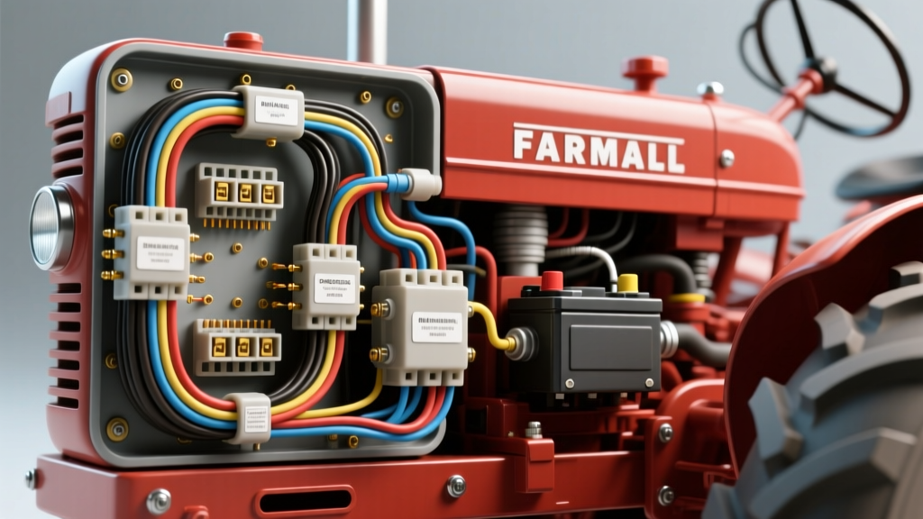
The Danger of Misinterpreting the Farmall Cub Wiring Diagram
The International Harvester Farmall Cub, produced from 1947 through 1981, is one of the most iconic and widely restored compact tractors in agricultural history. However, its electrical system is notoriously misunderstood. Because these tractors span multiple decades of engineering shifts—from 6-volt positive-ground generators to 12-volt negative-ground alternators—restorers and mechanics frequently rely on a generic wiring diagram for Farmall Cub tractors without accounting for the specific year, ignition type, or previous owner modifications. This leads to catastrophic electrical failures, melted harnesses, and severe fire hazards.
As an automotive and agricultural electrical specialist, I have inspected dozens of restored Cubs. The vast majority feature spliced wires, bypassed safety components, and incorrect grounding schemes. This guide details the most critical safety warnings and common wiring mistakes encountered when working on the Farmall Cub electrical system, providing actionable technical data to ensure your tractor operates safely and reliably.
Critical Safety Warnings Before You Cut a Single Wire
1. The Magneto Shock and Spark Hazard
Many early Farmall Cubs are equipped with a Fairbanks Morse or IH magneto rather than a battery-fed distributor. A magneto generates its own high-voltage spark independently of the tractor battery. Disconnecting the battery does not disable the ignition system. If you are working near the spark plug wires or the distributor cap while the engine is being cranked or rotated, you risk a severe high-voltage shock or accidental engine start. Always ground the magneto primary terminal to the chassis before performing wiring diagnostics.
2. Battery Disconnect and Capacitor Discharge
Before cutting, stripping, or testing any wire, you must physically remove the ground cable from the battery terminal. On original 6-volt positive-ground systems, this means removing the cable from the positive terminal. On converted 12-volt negative-ground systems, remove the negative cable. Furthermore, if your Cub is equipped with an electronic ignition conversion module, wait at least 60 seconds after battery disconnect to allow internal capacitors to discharge before probing the ignition coil terminals.
Top 5 Wiring Mistakes on the Farmall Cub (and How to Fix Them)
Mistake 1: Ammeter Wiring Reversal and Undersized Gauge
The ammeter is the central trunk of the Farmall Cub electrical system. All charging current from the generator or alternator, as well as all accessory draw, passes through this single gauge.
- The Mistake: Using 14 AWG or 16 AWG wire to connect the ammeter to the starter switch and generator. This creates a massive bottleneck. When the generator outputs 15+ amps, the undersized wire acts as a heating element, melting the insulation and causing dashboard fires.
- The Fix: The ammeter main feed must be wired using a minimum of 10 AWG stranded copper wire. Furthermore, wiring the ammeter backward won't necessarily cause a fire, but it will read 'Discharge' when the tractor is charging, leading to false diagnostic conclusions. Ensure the 'GEN' or 'ALT' terminal on the ammeter faces the charging source, and the 'BAT' terminal faces the starter switch/battery feed.
Mistake 2: Ignition Switch Terminal Misidentification (Magneto vs. Distributor)
This is arguably the most dangerous mistake made by restorers transitioning from automotive wiring to tractor wiring.
- Magneto Systems: The ignition switch on a magneto-equipped Cub is a grounding switch. It stops the engine by grounding the ungrounded side of the primary points to the chassis. If you wire a standard 12V automotive ignition switch (which feeds power) to a magneto, you will create a dead short to ground the moment you turn the key, potentially melting the harness or destroying the magneto coil.
- Battery Ignition (Distributor) Systems: These require a standard power-feed switch. Power flows from the ammeter, through the ignition switch, to the ignition coil.
- The Fix: Verify your ignition source. If using a magneto, use a simple single-pole single-throw (SPST) toggle switch that connects the magneto kill terminal directly to the tractor chassis. For detailed OEM schematics, refer to the TM Tractor Parts wiring diagram archives.
Mistake 3: Skipping the Ballast Resistor on 12V Conversions
When converting a 6-volt Farmall Cub to a 12-volt system (usually to accommodate an alternator and modern accessories), many mechanics leave the original 6-volt ignition coil in place and wire 12 volts directly to it.
- The Result: The 6-volt coil will overheat, the internal windings will short, and the distributor points will burn away within hours of operation due to excessive current arcing.
- The Fix: You must install a 1.5 to 1.8-ohm ballast resistor in series between the ignition switch and the positive terminal of the coil. Alternatively, replace the 6V coil with a true 12V coil that has an internal resistance of approximately 3.0 ohms.
Mistake 4: Failing to Polarize the Generator
If you are retaining the original 6-volt or 12-volt generator system and you disconnect the battery, replace the voltage regulator, or swap the ground polarity, the generator's residual magnetism may be reversed.
- The Danger: If the generator is not polarized to match the battery, the cutout relay will fail to close, or worse, it will weld shut. If it welds shut, the battery will discharge backward through the generator, spinning it like a motor and causing a severe electrical fire.
- The Fix (Polarization Procedure): With the engine off, disconnect the 'GEN' wire from the voltage regulator. Use a jumper wire to briefly touch the 'BAT' terminal of the regulator to the 'GEN' terminal. You should see a small spark. This aligns the generator's magnetic field with the battery. For more on IH generator systems, the Binder Planet technical forums offer extensive community-tested troubleshooting threads.
Mistake 5: Poor Grounding via Painted Chassis
The Farmall Cub relies heavily on the chassis and engine block for ground returns, particularly for the starter motor, lighting circuits, and the mechanical starter switch.
- The Mistake: Bolting the starter switch, headlight buckets, or taillight brackets directly over fresh powder coat or enamel paint. Paint is an electrical insulator. This results in severe voltage drop, dim lights, and sluggish starter cranking.
- The Fix: Use a wire wheel or sandpaper to remove all paint and rust down to bare, shiny metal at every grounding point. Apply a thin layer of dielectric grease over the bare metal connection after tightening the hardware to prevent future corrosion.
Farmall Cub Wire Gauge (AWG) and Routing Specifications
Adhering to proper American Wire Gauge (AWG) standards is non-negotiable, especially on 6-volt systems where amperage is doubled compared to 12-volt systems for the same wattage output. The following table outlines the minimum acceptable wire gauges for a standard Farmall Cub restoration, compliant with SAE J1128 low-tension primary cable standards.
| Circuit / Component | 6-Volt System (AWG) | 12-Volt Conversion (AWG) | Notes & Safety Warnings |
|---|---|---|---|
| Battery to Starter Switch | 1/0 AWG | 2 AWG | Must be stranded, oil-resistant copper. 6V starters draw up to 300A cranking. |
| Starter Switch to Starter Motor | 1/0 AWG | 2 AWG | Keep routing as short as physically possible to minimize voltage drop. |
| Ammeter Main Feed (Trunk) | 10 AWG | 12 AWG | Do not use solid core wire; vibration will cause fatigue and snapping. |
| Generator/Alt to Ammeter/Reg | 10 AWG | 12 AWG | Route away from exhaust manifold to prevent insulation melting. |
| Ignition Coil Feed | 14 AWG | 16 AWG (w/ Ballast) | Ensure primary wire is rated for high-temperature engine bay environments. |
| Headlights (Each) | 12 AWG | 14 AWG | Verify chassis ground at the light bucket; add a dedicated 14 AWG ground if rust is present. |
| Taillight / Dash Lights | 14 AWG | 16 AWG | Use weather-pack connectors if exposed to the elements. |
Ignition Coil Polarity: The Hidden Spark Killer
When reading a wiring diagram for Farmall Cub tractors, restorers often ignore coil polarity. Ignition coils are designed to operate with a specific polarity to maximize spark intensity. The spark plug center electrode is designed to be the negative side of the spark gap, as electrons flow more easily from a hot cathode to a cooler anode.
- On a 6-Volt Positive Ground System: The positive terminal of the battery is grounded. Therefore, the negative terminal of the ignition coil must connect to the distributor points, and the positive terminal connects to the ignition switch.
- On a 12-Volt Negative Ground Conversion: You must reverse the coil wiring. The positive terminal of the coil connects to the distributor points, and the negative terminal connects to the ignition switch.
Reversing the coil polarity will not immediately destroy the system, but it will reduce spark voltage by up to 20%, leading to hard starting, fouled plugs, and misfires under heavy load.
Summary: Verify Before You Energize
The Farmall Cub is a simple machine, but its electrical system demands respect and precision. Never assume that the wiring harness currently on the tractor matches the factory diagram. Previous owners frequently bypassed cutout relays, swapped magneto systems for distributors, or executed haphazard 12-volt conversions. Always trace every wire from end to end, verify your ground polarity, use the correct AWG wire sizes, and ensure your ignition switch matches your specific ignition source. By avoiding these common mistakes, you ensure your Farmall Cub remains a reliable piece of agricultural history rather than a rolling fire hazard.