Understanding the RV Inverter Topology and Safety Standards
Upgrading or installing an off-grid power system in a motorhome or travel trailer requires strict adherence to electrical safety codes. When referencing an inverter wiring diagram for RV applications, the complexity goes far beyond simply connecting positive and negative terminals to a battery bank. Recreational vehicles operate in high-vibration, high-temperature environments, making proper wire gauge selection, overcurrent protection, and chassis grounding critical to preventing electrical fires. According to NFPA 70 (National Electrical Code) Article 551, which governs Recreational Vehicles, all DC and AC wiring must be properly routed, protected from physical damage, and bonded to the chassis to ensure fault currents have a safe path to ground.
Modern RV pure sine wave inverters (typically ranging from 2000W to 4000W) serve a dual purpose: they invert 12V DC battery power into 120V AC for appliances, and they act as high-amperage battery chargers when connected to shore power. Therefore, the wiring schematic must account for bi-directional current flow on the DC side and seamless switching on the AC side via an Automatic Transfer Switch (ATS).
DC Conductor Sizing and Overcurrent Protection Chart
Voltage drop is the primary enemy of RV inverter efficiency. A high-wattage inverter pulling 3000W from a 12V nominal battery bank (which actually sits around 12.5V to 13.2V) will draw upwards of 250 amps under continuous load, and significantly more during surge events like starting a microwave compressor. To maintain a voltage drop of less than 0.5V, you must use properly sized stranded copper wire.
| Inverter Rating | Peak DC Draw (12V) | Min. AWG (Up to 5ft) | Min. AWG (5ft - 10ft) | Overcurrent Protection |
|---|---|---|---|---|
| 1000W | 105 Amps | 2 AWG | 1/0 AWG | 125A ANL Fuse |
| 2000W | 210 Amps | 1/0 AWG | 2/0 AWG | 250A ANL Fuse |
| 3000W | 315 Amps | 2/0 AWG | 3/0 AWG | 350A Class T Fuse |
| 4000W | 420 Amps | 3/0 AWG | 4/0 AWG | 400A Class T Fuse |
Note: Class T fuses are highly recommended over ANL fuses for systems exceeding 2000W due to their higher Ampere Interrupt Capacity (AIC), which is crucial for protecting against catastrophic short circuits in large lithium battery banks.
Step-by-Step Installation Guide
Step 1: DC Input Routing and Termination
The DC side of your inverter wiring diagram for RV setups begins at the battery bank. Use SAE J1128 compliant stranded copper wire (Red for DC+, Black for DC-). Strip the insulation using a precision wire stripper to avoid nicking the copper strands, which creates localized resistance and heat. Crimp heavy-duty copper lugs using a hydraulic hex crimper to ensure a gas-tight connection. Cover the crimp joint with 3:1 adhesive-lined marine heat shrink to prevent moisture ingress and corrosion. Mount the main DC overcurrent fuse (e.g., 250A Class T) on the positive leg within 18 inches of the battery bank positive terminal, as mandated by ABYC and NEC guidelines. Torque the inverter DC terminal busbars to the manufacturer's exact specification—typically between 12 and 15 ft-lbs for 2/0 AWG lugs.
Step 2: AC Integration via Automatic Transfer Switch (ATS)
The AC output of the inverter must feed your RV's main AC breaker panel. In a standard RV inverter wiring diagram, the inverter's 120V AC output is wired to the 'Generator' or 'Secondary' input terminals of a 30-Amp or 50-Amp Automatic Transfer Switch. The shore power cord feeds the 'Primary' input. When shore power is disconnected, the ATS defaults to the inverter output. Use 10 AWG stranded THHN wire for 30A systems and 6 AWG for 50A systems. Ensure the AC Hot (Black), Neutral (White), and Ground (Green) are strictly isolated from the DC side and properly landed on the ATS terminal blocks. Never wire the inverter AC output directly in parallel with the shore power input without an ATS or internal transfer relay, as backfeeding shore power can destroy the inverter and pose a lethal hazard to utility workers.
Step 3: Chassis Grounding and Neutral Bonding
The most misunderstood aspect of RV inverter installation is the Neutral-to-Ground bond. According to Magnum Energy and Sensata technical bulletins, an RV is considered a 'separately derived system' when running off the inverter. Therefore, the inverter must internally bond the AC Neutral to the AC Ground, which is then tied to the RV's bare copper chassis ground. However, when plugged into shore power, the neutral-ground bond occurs at the campground pedestal, and the inverter must isolate its internal bond to prevent parallel neutral currents. Premium RV inverters feature an automatic internal relay that handles this bonding and unbonding dynamically. You must connect a minimum 6 AWG (or matching DC negative size) bare copper grounding wire from the inverter's designated chassis ground lug directly to the RV's main steel chassis frame using a star washer and self-tapping bolt to bite through the paint and ensure a zero-ohm connection.
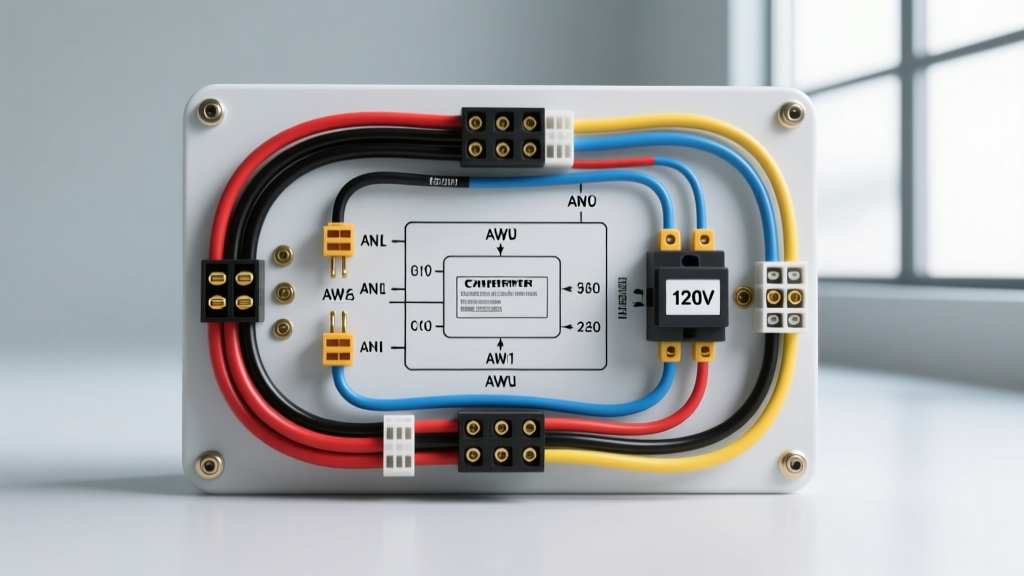
Visualizing the Inverter Wiring Diagram for RV Systems
To conceptualize the schematic, trace the power flow through these primary nodes:
- Node A (Battery Bank): 12V DC+ travels through a 250A Class T fuse via 2/0 AWG Red wire to the Inverter DC+ Busbar.
- Node B (Inverter DC-): 2/0 AWG Black wire travels from the Inverter DC- Busbar to a 500A DC Shunt (for battery monitoring), then to the negative busbar, and finally to the battery bank.
- Node C (Inverter AC Out): 10 AWG Black (Hot), White (Neutral), and Green (Ground) exit the inverter's internal transfer relay and terminate at the ATS 'Source 2' input.
- Node D (Shore Power In): 30A Shore cord terminates at ATS 'Source 1' input.
- Node E (Main Panel): ATS Output feeds the RV AC Subpanel, distributing power to GFCI outlets, the microwave, and the AC-to-DC converter.
Troubleshooting Common Installation Faults
Even with a perfect inverter wiring diagram for RV applications, installation errors can cause frustrating fault codes. Use this diagnostic tree to resolve common issues:
1. GFCI Outlets Tripping Randomly on Inverter Power
Cause: Improper Neutral-Ground bonding. If the inverter is a modified sine wave unit, or if the internal neutral-ground relay has failed, the GFCI outlets will detect a ground fault.
Fix: Verify the inverter is a Pure Sine Wave model. Check the inverter's DIP switch settings or software configuration to ensure 'Neutral-Ground Relay' is enabled. Test the continuity between AC Neutral and AC Ground at the outlet while the inverter is running; it should read less than 1 ohm.
2. Inverter Shuts Down Under Heavy Load (Low Battery Cutoff)
Cause: Excessive DC voltage drop. The inverter 'sees' a low voltage at its terminals because the wire is undersized, the crimps are loose, or the battery bank is degraded.
Fix: Use a digital multimeter to measure DC voltage directly at the battery terminals, then measure again at the inverter DC busbars while the microwave is running. If the difference exceeds 0.5V, you must upgrade your AWG wire size, shorten the cable run, or re-crimp the lugs.
3. Shore Power Fails to Charge Batteries
Cause: ATS failure or miswired AC inputs.
Fix: Verify 120V AC is present at the ATS 'Source 1' input. If present, but not reaching the inverter's AC input terminals, the ATS relay may be stuck, or the 10 AWG jumper wires between the ATS and the inverter AC-In lug have vibrated loose. Tighten all AC terminal screws to 25 in-lbs.
Authoritative References
For further reading on RV electrical standards and inverter sizing, consult the following resources:
- National Fire Protection Association (NFPA) - NFPA 70: National Electrical Code, Article 551 (Recreational Vehicles and Recreational Vehicle Parks).
- Sensata Technologies / Magnum Energy - Magnum Inverter/Charger Installation and Configuration Manuals.
- SAE International - SAE J1128: Low Tension Primary Cable Standard for automotive and RV DC wiring.