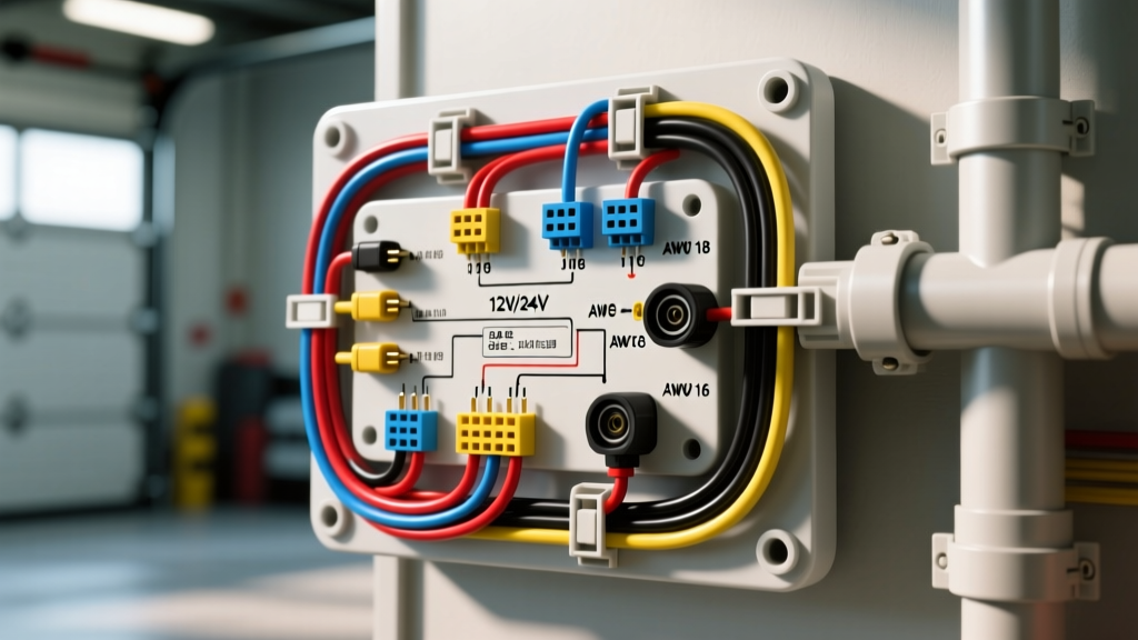
Understanding the Mobile Wiring Diagram of CCTV Camera Systems
When transitioning from residential security to automotive surveillance, interpreting the wiring diagram of cctv camera setups requires a fundamental shift in electrical engineering. Whether you are outfitting a Class 8 commercial truck, a fleet of last-mile delivery vans, or a Class A motorhome, mobile digital video recorders (MDVRs) and their associated cameras face extreme electrical and physical environments. This beginner-friendly guide breaks down the core schematics, wire gauges, and connector pinouts necessary to install a reliable vehicle CCTV system that survives alternator whine, voltage spikes, and chassis vibration.
Why Automotive CCTV Wiring Differs from Residential
In a static building, a CCTV camera simply plugs into a 12V DC transformer or utilizes Power over Ethernet (PoE). In a vehicle, the electrical system is a hostile environment. A standard 12V automotive system can experience voltage fluctuations ranging from 9V during engine cranking to over 100V during a load dump event (when the battery disconnects while the alternator is charging). Furthermore, the vehicle chassis acts as a dynamic ground plane, introducing electromagnetic interference (EMI) from the alternator, ignition coils, and high-current switching solenoids. Therefore, a proper mobile CCTV wiring diagram must incorporate isolated grounds, transient voltage suppression, and shielded cabling.
Core Components of a Mobile CCTV Wiring Diagram
A complete vehicle surveillance schematic consists of three primary circuits: the power distribution network, the video/data signal routing, and the trigger/sensor inputs. Let us break down each subsystem from the perspective of an automotive electrical technician.
1. Power Distribution and Load Dump Protection
Never wire an MDVR or mobile camera directly to the battery without proper fusing and transient protection. According to SAE J1455 standards for heavy-duty truck electrical systems, commercial vehicles are subject to severe voltage transients. Your wiring diagram should show the main power feed originating from the battery positive terminal, passing through a master circuit breaker or ANL fuse, and then entering a relay-controlled fuse block.
- Constant 12V/24V (B+): Powers the MDVR's internal battery backup and maintains the real-time clock. Fused at 5A.
- Ignition Switched 12V/24V (ACC): Triggers the MDVR to begin recording and powers the camera array. Fused at 10A-15A depending on the number of IR (Infrared) cameras.
- System Ground (GND): Must be tied directly to the vehicle's main chassis ground stud using a minimum 12 AWG wire. Do not rely on sheet metal screws for MDVR grounding.
2. Standard Mobile Camera Pinouts
Most automotive CCTV systems utilize either 4-pin GX16 'aviation' connectors or ruggedized M12 connectors to ensure waterproof, vibration-resistant mating. These connectors combine power, ground, video, and audio into a single shielded cable jacket. Below is the industry-standard pinout configuration for analog and AHD (Analog High Definition) mobile cameras:
| Pin | Function | Standard Wire Color | Specification / Notes |
|---|---|---|---|
| 1 | Power (VCC) | Red | 12V or 24V DC (Regulated via MDVR internal PSU) |
| 2 | Ground (GND) | Black | Must tie to MDVR ground, NOT local chassis ground |
| 3 | Video Signal | Yellow | Coaxial center conductor (75 Ohm impedance) |
| 4 | Audio / Trigger | White | Microphone bias voltage or reverse-gear trigger |
Expert Note: Pin 2 (Ground) must run all the way back to the MDVR. If you ground the camera locally to the trailer or rear chassis, you will create a ground loop. Because the alternator charges the battery at the front of the vehicle, the voltage potential between the front chassis and rear chassis fluctuates, resulting in severe 'alternator whine' on the audio channel and rolling horizontal bars on the video feed.
Wire Gauge (AWG) and Routing Specifications
Selecting the correct American Wire Gauge (AWG) is critical in long-wheelbase vehicles like school buses, RVs, and semi-trucks. Voltage drop over long distances can cause IR cameras to fail at night when their infrared LEDs draw maximum current. Primary wire insulation must meet SAE J1128 specifications for high-temperature, oil-resistant automotive environments (typically cross-linked polyethylene or XLPE).
AWG Sizing Chart for Mobile Camera Runs
| Cable Run Length | Camera Type | Max Current Draw | Recommended AWG (Power) | Recommended AWG (Signal) |
|---|---|---|---|---|
| Under 10 ft | Standard Dome (Day) | 0.5A | 18 AWG | 22 AWG Shielded |
| 10 - 25 ft | IR Night Vision Cam | 1.5A | 16 AWG | 20 AWG Shielded |
| 25 - 40 ft | PTZ Mobile Camera | 3.0A (Peak) | 14 AWG | 18 AWG Twisted Pair |
| 40 - 60 ft (Trailer) | Multi-Cam Trunk Line | 8.0A+ | 12 AWG | RG59 Coax / Cat6 STP |
Signal Routing and EMI Mitigation
Electromagnetic compatibility (EMC) is a major factor in mobile video. Per SAE J1113 EMC testing standards, sensitive signal wires must be isolated from high-current noise generators. When routing your CCTV camera cables:
- Never run video cables parallel to the alternator output cable or starter motor cables. Maintain a minimum 6-inch separation.
- If crossing high-current cables is unavoidable, cross them at a strict 90-degree angle.
- For PTZ (Pan-Tilt-Zoom) cameras utilizing RS485 data protocols, always use Shielded Twisted Pair (STP) cabling. The shield must be grounded at the MDVR end only (drain wire) to prevent ground loops while dissipating induced RF interference.
Connector Terminations and Physical Security
Vibration is the enemy of mobile wiring. Standard residential crimp connectors and electrical tape will fail within months on a commercial truck. For power distribution to the MDVR, use Deutsch DT or DTM series connectors. These feature silicone seals and copper alloy pins that resist moisture ingress and vibration-induced fretting corrosion.
For inline splices in the camera harness, soldering is mandatory. However, solder alone can become brittle and snap under chassis flex. You must seal the solder joint using dual-wall adhesive-lined heat shrink tubing (often referred to as marine heat shrink). The inner meltable adhesive layer creates a waterproof seal and provides mechanical strain relief, ensuring the wiring diagram's integrity is maintained physically, not just electrically.
Troubleshooting Common Mobile CCTV Failure Modes
Even with a perfect schematic, real-world installations encounter issues. Use this symptom-cause-fix decision tree to diagnose mobile CCTV faults:
Symptom: Rolling Horizontal Bars on Video Feed
- Cause: Ground Loop. The camera ground is referencing a different voltage potential than the MDVR ground.
- Fix: Verify Pin 2 continuity from the camera pigtail back to the MDVR harness. Ensure the camera housing is isolated from the metal mounting bracket using nylon washers.
Symptom: Camera Reboots or Drops Offline at Night
- Cause: Voltage Drop. When the IR LEDs activate, current draw spikes. If the wire gauge is too thin for the distance, voltage at the camera drops below the 10.5V operational threshold.
- Fix: Measure voltage at the camera pigtail with the IR LEDs active. If below 11V, upgrade the power conductors by one AWG size (e.g., from 18 AWG to 16 AWG) or install a local 12V voltage regulator.
Symptom: Severe Audio Whine Synchronized with Engine RPM
- Cause: Alternator EMI bleeding into the audio signal wire due to poor shielding or shared ground paths.
- Fix: Replace the camera harness with properly shielded cable. Ensure the shield drain wire is terminated exclusively at the MDVR ground bus, and verify the MDVR is grounded directly to the battery negative terminal or main chassis ground stud.
Conclusion
Designing and executing a flawless wiring diagram of cctv camera systems for vehicles requires respecting the harsh realities of automotive electrical networks. By adhering to SAE standards, utilizing proper AWG sizing, isolating signal grounds, and employing vibration-proof connectors like Deutsch and M12, you ensure your mobile surveillance system provides crystal-clear footage regardless of the environment. Always document your specific pinouts, fuse ratings, and routing paths on a master schematic kept inside the vehicle's maintenance binder for future troubleshooting.