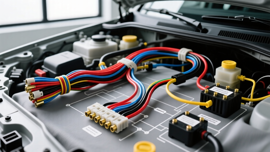
Navigating the International 4700 Electrical Labyrinth
Medium-duty workhorses like the International 4700 (particularly the 1995–2003 models equipped with the DT466E and T444E engines) are legendary for their mechanical durability. However, their electrical systems—complete with early multiplexing, Allison transmission integrations, and Bosch engine control modules (ECMs)—can be a nightmare to diagnose without the correct documentation. When a truck throws a phantom SID 250 (Engine Data Link) fault or experiences intermittent injector misfires, guessing is not an option. You need an accurate international 4700 wiring diagram pdf.
But not all wiring diagrams are created equal. A faded, third-generation photocopy found on a trucking forum is vastly different from a factory-issued Navistar ISIS schematic. In this guide, we compare the top sources for International 4700 wiring diagram PDFs, evaluating them on accuracy, depth, and real-world utility for heavy-duty electrical troubleshooting.
Why the Right Wiring Diagram PDF Matters
The International 4700 chassis relies on a complex network of sensors, relays, and data buses. Unlike light-duty passenger vehicles, medium-duty trucks feature modular harnesses that pass through heavy-duty bulkhead connectors. A proper diagram must provide not just the circuit path, but the exact connector cavity number, wire gauge (AWG), and OEM color code. Using an incomplete diagram can lead to misdiagnosing a failed ECM when the actual culprit is a corroded pin in the 120-way engine-to-chassis connector.
Comparing the Top International 4700 Wiring Diagram PDF Sources
1. OEM Navistar Service Information (ISIS / ServiceMaxx)
The gold standard for any International truck is the factory documentation. Navistar’s proprietary systems provide dynamic, highly detailed schematics. When exported to PDF, these diagrams include exact splice locations (e.g., Splice S142), ground stud locations (e.g., G104 behind the left headlight), and connector end-views.
- Pros: 100% accurate wire colors, includes connector cavity views, features step-by-pin diagnostic flowcharts.
- Cons: Expensive; typically requires a dealership login or a high-tier commercial subscription.
- Best For: Complete harness rebuilds, chasing parasitic draws, and ECM pinout verification.
2. Mitchell 1 TruckSeries / ProDemand
Mitchell 1 is the industry standard for independent commercial repair shops. Their TruckSeries platform flattens OEM diagrams into standardized, easy-to-read formats. While they may occasionally simplify complex multiplexed networks, their coverage of the DT466E and Allison 1000/3000 series interfaces is excellent.
- Pros: Standardized symbols, excellent component location guides, integrates with repair procedures.
- Cons: Lacks the granular connector cavity/pin-shape diagrams found in OEM docs.
- Best For: Daily shop use, component testing, and quick circuit continuity checks.
3. Free Forum & Third-Party PDF Repositories
A quick web search will yield dozens of free International 4700 wiring diagram PDF links hosted on forums or document-sharing sites. These are usually scanned pages from older printed service manuals.
- Pros: Free and immediately accessible.
- Cons: Often blurry, missing the critical legend page, or worse, sourced from a different sub-model (like a 4900 with a different transmission setup), leading to dangerous miswiring.
- Best For: Basic fuse/relay identification and emergency roadside reference.
Source Comparison Matrix
| Feature | OEM Navistar ISIS | Mitchell 1 TruckSeries | Free Forum PDFs |
|---|---|---|---|
| Connector Cavity Views | Yes | No | Rarely |
| Wire Color Accuracy | 100% OEM | 95% (May vary by year) | Low (Faded/Scanned) |
| Splice & Ground Locations | Exact Coordinates | General Area | Missing |
| Cost | High (Dealer/Shop) | Medium (Sub) | Free |
Technical Deep Dive: DT466E Injector Harness & Pinouts
To understand why premium diagrams are necessary, consider the DT466E Electronic Unit Injector (EUI) harness. The ECM fires these injectors using high-voltage, low-current pulses. If you are using a subpar PDF, you might misidentify the high-side and low-side control wires, leading to a blown ECM driver.
Below is a reference table for the primary DT466E ECM-to-Injector harness connections. Always verify against your specific model year's Navistar Service Portal documentation, as mid-year production changes do occur.
| Circuit Function | ECM Pin | OEM Wire Color | AWG | Diagnostic Notes |
|---|---|---|---|---|
| Injector 1 High | 1 | Red/White | 18 | Solenoid Feed (Check for 0.5 - 1.0 ohms) |
| Injector 1 Low | 2 | Red/Black | 18 | Solenoid Return |
| Injector 2 High | 3 | White/Red | 18 | Solenoid Feed |
| Injector 2 Low | 4 | White/Black | 18 | Solenoid Return |
| Camshaft Position (CMP) | 14 | Gray | 20 | Hall Effect; verify 5V reference & ground |
| ECM Main Power | 45 | Red | 12 | Switched Battery via Main Relay |
| ECM Chassis Ground | 60 | Black | 10 | Must have < 0.05V drop under load |
Allison Transmission & SAE J1939 Databus Integration
Many International 4700s are paired with Allison 1000, 2000, or 3000 series transmissions. The electrical integration between the Navistar chassis ECM and the Allison Transmission Control Module (TCM) relies heavily on the SAE J1939 CAN bus network.
When diagnosing shift solenoids or communication faults (like SID 231), your wiring diagram PDF must clearly delineate the CAN High (typically Yellow) and CAN Low (typically Green) twisted pair circuits. These circuits require strict adherence to twisting ratios and rely on 120-ohm terminating resistors located at the ECM and the instrument cluster. A generic PDF will rarely show the exact physical location of these terminating resistors, leading technicians on wild goose chases replacing perfectly good TCMs.
Common Failure Modes in the 4700 Chassis Harness
Armed with a high-quality wiring diagram, focus your diagnostics on these known International 4700 failure points:
- The 120-Pin Bulkhead Connector: Located on the firewall, this massive connector routes engine bay harnesses into the cab. It is highly susceptible to capillary wicking. If the engine-side harness is exposed to road salt and moisture, corrosion can travel up the wire strands and into the cab-side pins. Fix: Depin the connector using a proper Deutsch extraction tool, clean with electrical contact cleaner, and apply dielectric grease. Never use a pick to force pins out, as this damages the retention tangs.
- Ground Stud G104 Oxidation: The primary ECM and sensor ground is often tied to the chassis near the left front frame rail. Over time, dissimilar metal corrosion builds up between the copper ring terminal and the steel chassis. Fix: Remove the M8 nut, wire-wheel the chassis to bare metal, apply a zinc-rich primer, and re-torque the ground stud to 25 Nm (18 lb-ft).
- Allison Pass-Through Connector: The harness connecting the cab TCM to the transmission case pass-through connector suffers from extreme heat and vibration. The internal rubber seals harden, allowing transmission fluid to wick into the shift solenoid wiring (Pins A through E). Fix: Inspect for fluid in the connector cavity. If ATF is present, the internal transmission harness must be replaced.
Final Verdict: Selecting Your Diagram Resource
If you are an owner-operator doing basic maintenance or replacing a headlight relay, a free international 4700 wiring diagram pdf from a reputable trucking forum might suffice. However, if you are diagnosing a no-start condition on a DT466E, chasing a J1939 datalink fault, or rebuilding a corroded bulkhead connector, investing in access to OEM Navistar ISIS or Mitchell 1 TruckSeries is non-negotiable. The time saved by having accurate connector cavity views, precise AWG specifications, and verified ground locations will pay for the subscription cost on your very first diagnostic job.