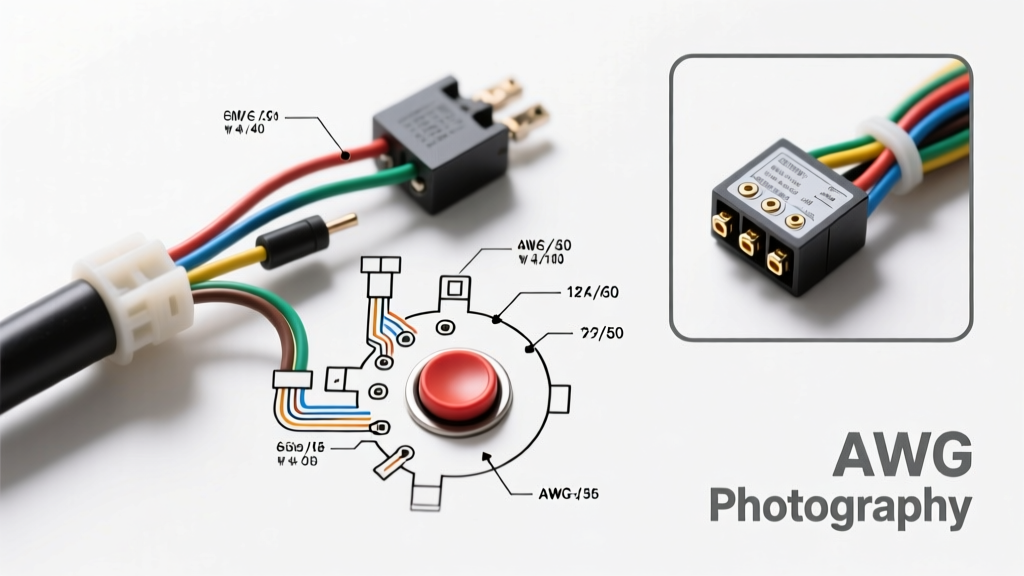
Understanding the Basic Push Button Horn Wiring Diagram
When upgrading your vehicle's acoustic output from a weak factory snail horn to high-decibel electric discs or dual air horns, you cannot simply splice into the existing factory wiring. Factory horn circuits are engineered for low-amperage electromechanical disc horns, typically drawing between 5 and 8 amps. In contrast, aftermarket setups like Fiamm Freeway Blasters, Hella Supertones, or Viair air compressors can draw anywhere from 15 to 30 amps combined. Pushing this massive current through the delicate factory steering wheel clockspring ribbon and Body Control Module (BCM) multiplex switches will result in immediate thermal failure, melted clockspring traces, or fried logic boards.
The solution is utilizing a basic push button horn wiring diagram that incorporates a standard ISO 4-pin automotive relay. This diagram isolates the high-current load circuit from the low-current switch circuit, allowing your push button or factory steering wheel pad to safely trigger the relay coil without bearing the electrical burden of the horn itself. Below is a comprehensive, expert-level guide to executing this installation flawlessly.
Component and Wire Gauge Specifications
Using the correct American Wire Gauge (AWG) is critical to preventing voltage drop and ensuring your horns receive the full 12V required to reach their maximum decibel rating. Refer to the specification chart below for your materials list.
| Circuit Function | AWG Size | Standard Wire Color | Terminal Type | Fuse / Rating |
|---|---|---|---|---|
| Battery to Relay (Pin 30) | 12 AWG (or 10 AWG for air compressors) | Red | Ring Terminal / 1/4' Spade | 20A or 30A ATO Inline |
| Relay to Horn (Pin 87) | 12 AWG | Blue | 1/4' Female Spade | N/A (Protected by Pin 30) |
| Relay Ground (Pin 85) | 18 AWG | Black | Ring Terminal (Star Washer) | N/A |
| Switch Trigger (Pin 86) | 18 AWG | Green or Yellow | Quick Splice / Solder Seal | Tapped from Ignition Source |
Step-by-Step Relay Wiring Instructions
Follow these precise steps to wire the relay, which serves as the electromagnetic bridge in your basic push button horn wiring diagram.
- Mount the Relay: Secure the 12V relay in the engine bay, preferably near the battery or the horn mounting location. Keep it away from extreme heat sources like exhaust manifolds. Use a relay harness with a built-in fuse holder for Pin 30 to simplify the process and ensure safety.
- Wire Pin 30 (Constant 12V Power): Run a 12 AWG red wire from the positive battery terminal to Pin 30 on the relay. You must install an inline ATO fuse holder within 6 inches of the battery connection. For dual electric horns, use a 20A fuse; for heavy-duty air compressors, step up to 10 AWG wire and a 30A fuse.
- Wire Pin 87 (Load to Horn): Connect a 12 AWG blue wire from Pin 87 to the positive terminal of your aftermarket horn. If you are running dual horns, use a weatherproof distribution block or a sealed parallel splice to send power to both units simultaneously. Ensure the negative terminal of the horn is grounded directly to a clean, bare-metal chassis point using a dedicated 12 AWG ground wire.
- Wire Pin 85 (Relay Ground): Run an 18 AWG black wire from Pin 85 to a solid chassis ground. Scrape away any paint, undercoating, or rust to ensure bare metal contact. Use a ring terminal secured with a bolt and a star lock washer to prevent vibration-induced loosening.
- Wire Pin 86 (Switch Trigger): This pin receives the low-current 12V signal from your push button switch. The integration method depends on whether you are using an aftermarket dash button or retaining the factory steering wheel horn pad (detailed below).
Integrating the Push Button Switch
Scenario A: Aftermarket Dash-Mounted Push Button
If you are installing a momentary push button on the dashboard or center console, you must wire it to handle the trigger current. Run an 18 AWG wire from a switched 12V ignition source (such as the back of the cigarette lighter or accessory fuse panel) to one terminal of your push button. Run a second 18 AWG wire from the other terminal of the push button directly to Pin 86 on the relay. When you press the button, it completes the circuit, energizing the relay coil and closing the high-current contacts between Pins 30 and 87.
Scenario B: Retaining the Factory Steering Wheel Horn Pad
To keep your factory steering wheel button functional, you must tap into the existing horn trigger wire. This wire typically exits the steering column clockspring and travels to the BCM or a dedicated horn relay in the under-hood fuse box. Using a digital multimeter, probe the factory horn wire while an assistant presses the steering wheel pad. You are looking for a wire that shows 0V at rest and jumps to 12V when pressed (or drops to 0V if the vehicle uses a ground-switched multiplex system). If it is a 12V positive trigger, splice your 18 AWG Pin 86 wire into this factory trigger wire using a solder-seal butt connector.
Protecting Sensitive Electronics: The Flyback Diode
When wiring Pin 86 to a modern vehicle's BCM or ECU logic gate, you must protect the vehicle's sensitive computers from inductive kickback. When the relay coil de-energizes (you release the horn button), the collapsing magnetic field inside the relay generates a high-voltage reverse spike that travels back down the trigger wire. Over time, this spike can fry the internal driver circuit of your BCM. To prevent this, solder a standard 1N4001 rectifier diode across Pins 85 and 86. The silver stripe on the diode must point toward Pin 86 (the 12V trigger side). This creates a one-way valve that safely recirculates the voltage spike back into the relay coil, completely neutralizing the threat to your vehicle's computers.
Crimping and Weatherproofing Best Practices
The engine bay is a hostile environment characterized by extreme temperature cycling, moisture, and high-frequency vibration. Never use solder alone for under-hood wiring connections. Solder wicks up into stranded copper wire, creating a rigid stress point that will eventually snap under engine vibration. Instead, use a high-quality ratcheting crimper for all mechanical connections. For ultimate reliability, use adhesive-lined marine-grade heat shrink terminals. When heated, the inner thermoplastic adhesive melts and seals the wire barrel, completely blocking moisture ingress and preventing the green corrosion that causes high-resistance voltage drops.
Troubleshooting Common Horn Wiring Failures
- Symptom: Relay clicks loudly, but horn does not sound.
Cause: Voltage drop on the high-current circuit. The relay coil requires only 150mA to click, but the horn needs 15A+ to sound. Fix: Use a multimeter to measure voltage at the horn terminal while the button is pressed. If it reads below 10.5V, upgrade the Pin 30 and Pin 87 wiring to a thicker gauge (e.g., 10 AWG) and check for corrosion at the battery terminal and chassis grounds. - Symptom: Horn stays on continuously after releasing the button.
Cause: The internal contacts of the relay have welded together due to excessive arcing, or the trigger wire on Pin 86 is shorted to a constant 12V source. Fix: Disconnect the trigger wire from Pin 86. If the horn stops, you have a short in your push button switch wiring. If the horn continues to sound, the relay is permanently fused and must be replaced with a higher-rated unit (e.g., a 40A Bosch-style relay). - Symptom: Horn sounds weak or distorted.
Cause: Poor grounding at the horn itself. Many installers rely on the mounting bracket for the ground path, which is often compromised by powder coating, rust, or rubber isolation bushings. Fix: Run a dedicated 12 AWG ground wire directly from the negative terminal of the horn to a verified clean-metal chassis point.
Authoritative References
For further technical validation on automotive relay standards and diagnostic procedures, consult the following industry resources:
- SAE J559 Standard for 12V Automotive Relays - Society of Automotive Engineers guidelines on relay terminal numbering, coil resistance, and contact ratings.
- AA1Car Relay Diagnostics and Wiring - Comprehensive troubleshooting matrices for ISO mini-relays and multiplexed horn circuits.