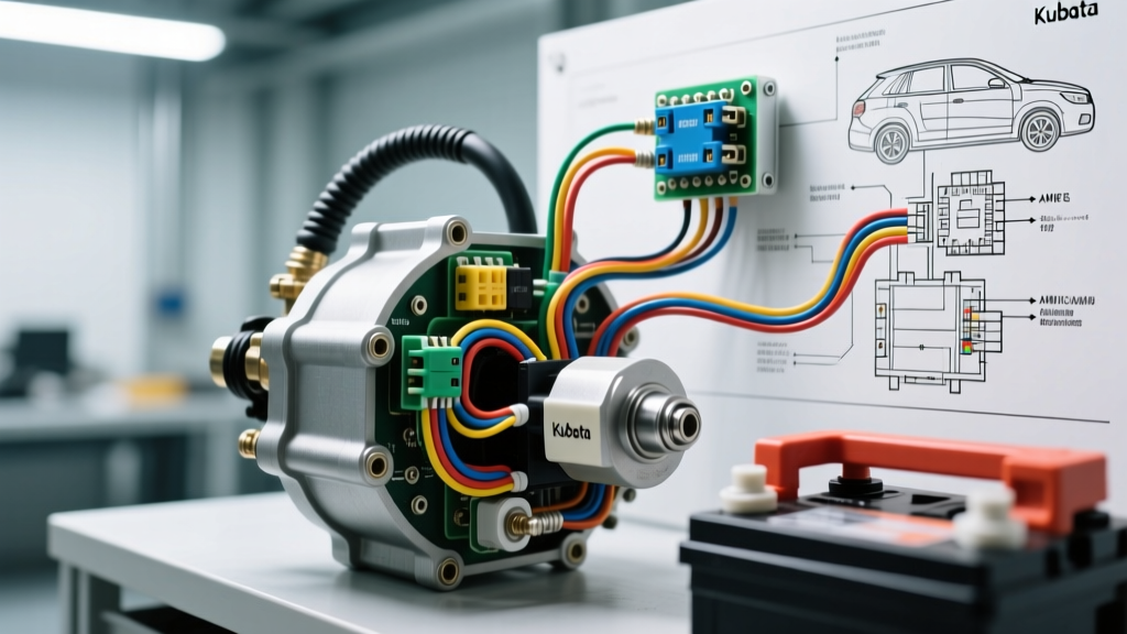
Decoding the Standard Kubota Starter Wiring Diagram
When maintaining or upgrading heavy-duty compact tractors, understanding the exact Kubota starter wiring diagram is critical for reliable cold-weather cranking and long-term electrical health. Whether you are working on a B-series, L-series, or M-series tractor powered by a D902, V1505, or V2203 diesel engine, the fundamental 12-volt starter circuit relies on three primary connections: the B-Terminal (Battery), the S-Terminal (Solenoid Trigger), and the chassis ground. Unlike modern automotive systems that rely heavily on CAN-bus messaging, most Kubota agricultural and industrial tractors utilize a traditional, hard-wired analog cranking circuit integrated with mechanical safety interlocks.
The main battery feed travels from the positive battery post via a heavy-gauge cable directly to the starter’s B-Terminal, typically an M10 copper stud. The S-Terminal, usually a male spade or M5/M6 threaded post depending on the starter model, receives a 12V trigger signal from the ignition switch. However, this trigger wire does not run directly from the key cylinder. According to official Kubota service documentation, the S-Terminal trigger circuit is routed through a series of safety interlock switches—including the transmission neutral safety switch, the PTO engagement switch, and on newer models, the operator seat presence switch. If any of these switches fail or are out of adjustment, the S-Terminal receives zero voltage, resulting in a no-crank condition that is frequently misdiagnosed as a dead starter.
Product Selection: OEM Direct Drive vs. High-Torque Gear Reduction
When replacing a failed starter on a Kubota diesel, technicians and owners face a primary selection dilemma: stick with the OEM Denso direct-drive unit or upgrade to an aftermarket High-Torque Gear Reduction (HTGR) starter. This decision drastically impacts your wiring requirements, current draw, and cold-cranking performance.
| Feature | OEM Denso Direct Drive (1.4kW - 1.7kW) | Aftermarket Gear Reduction (2.0kW - 2.2kW) |
|---|---|---|
| Internal Mechanism | Direct armature-to-pinion drive | Planetary gear set (approx. 4:1 ratio) |
| Locked Rotor Current Draw | 350A - 450A | 180A - 250A |
| Cranking Torque | Moderate (drops significantly under high compression) | High (multiplied by gear reduction) |
| Weight & Size | Heavy, large cylindrical housing | Compact, lighter, offset motor housing |
| Wiring Impact | Requires maximum AWG battery cables to prevent voltage drop | Lower amperage draw reduces strain on factory wiring harness |
For older Kubota tractors operating in freezing climates, the gear reduction starter is the superior selection. Because diesel engines require high cranking RPMs to achieve the cylinder heat necessary for compression ignition, the planetary gear reduction allows the starter motor to spin at high RPMs while multiplying the torque delivered to the flywheel ring gear. Furthermore, as noted by Denso's automotive electrical engineering guidelines, gear reduction starters draw significantly less amperage from the battery, which reduces voltage drop across the tractor's wiring harness and preserves the life of the ignition switch and safety interlock relays.
The Starter Relay Upgrade: Solving S-Terminal Voltage Drop
A common failure mode in the Kubota starter wiring diagram is voltage drop at the S-Terminal. Factory wiring often utilizes 14 AWG or 16 AWG wire for the trigger circuit, routing it through decades-old ignition switch contacts and multiple safety switches. By the time the 12V signal reaches the starter solenoid, it may have dropped to 9V or 8V. While 8V might be enough to pull the solenoid plunger inward (causing a loud 'click'), it often lacks the amperage required to close the heavy-duty internal contactor that bridges the B-Terminal to the motor windings.
The Expert Fix: When selecting and installing a new starter, especially a high-torque aftermarket unit, install a standard 30A Bosch-style 12V relay in the engine bay. Run a new 10 AWG fused wire directly from the B-Terminal to Pin 30 of the relay. Connect the factory S-Terminal trigger wire to Pin 86 (coil ground to chassis, coil power from Pin 85). Connect Pin 87 directly to the starter's S-Terminal. This allows the weak factory trigger signal to simply switch the relay coil, while the heavy 10 AWG wire delivers a full, unimpeded 12V and high amperage directly to the solenoid, guaranteeing instantaneous engagement.
AWG Cable Sizing and Terminal Specifications
Selecting the correct battery cable gauge is non-negotiable when wiring a Kubota starter. Undersized cables will overheat, melt the insulation, and starve the starter of the amperage required to overcome engine compression. According to SAE Standard J1128 for battery cable selection, wire gauge must be determined by the maximum current draw and the total length of the cable run (positive plus ground return).
| Starter Type | Max Current Draw | Cable Run (One Way) | Minimum Required AWG | Recommended Terminal Type |
|---|---|---|---|---|
| OEM 1.4kW Direct Drive | 400A | Under 48 inches | 1/0 AWG | Heavy-duty copper lug, M10 stud |
| OEM 1.4kW Direct Drive | 400A | Over 48 inches | 2/0 AWG | Heavy-duty copper lug, M10 stud |
| 2.2kW Gear Reduction | 250A | Under 60 inches | 2 AWG | Heavy-duty copper lug, M10 stud |
| Solenoid Trigger Wire | 5A - 15A | N/A | 12 AWG (Primary) / 14 AWG (Factory) | Insulated female spade or M5 ring |
Always use fine-strand, pure copper welding cable rather than standard automotive primary wire for the main B-Terminal feeds. Fine-strand copper offers superior flexibility and lower DC resistance, which is vital for the high-amperage, short-duration bursts required by diesel starters. Ensure all lugs are crimped with a hex-crimper and sealed with adhesive-lined heat shrink to prevent moisture ingress and terminal corrosion.
Diagnostic Decision Tree: Troubleshooting the Crank Circuit
Before replacing a starter based on a wiring diagram, perform these systematic electrical tests to isolate the failure point.
- Symptom: Complete Silence (No Click, No Crank)
- Step 1: Check battery voltage at rest (must be >12.4V).
- Step 2: Use a multimeter to check for 12V at the starter S-Terminal while an assistant holds the key in the 'START' position.
- Step 3: If 0V at S-Terminal, the fault is upstream. Bypass the PTO and Neutral safety switches temporarily to verify interlock failure.
- Step 4: If 12V is present at S-Terminal but no click occurs, the solenoid coil is open (internally broken) or the starter ground path is compromised. Check the engine-to-chassis ground strap.
- Symptom: Loud 'Click' but No Engine Rotation
- Step 1: Perform a voltage drop test across the main battery cables. Place multimeter probes on the battery post and the corresponding cable end at the starter B-Terminal while cranking. A drop greater than 0.2V indicates a corroded or undersized cable.
- Step 2: Check voltage at the battery during the 'click'. If battery voltage drops below 9.5V, the battery has a bad cell or is severely discharged.
- Step 3: If battery and cables test good, the starter's internal contactor is likely pitted and failing to pass current to the armature, or the engine is mechanically seized (hydro-locked).
- Symptom: Starter Spins but Does Not Engage Flywheel (Freewheeling)
- Step 1: Inspect the Bendix drive or gear-reduction pinion. If the pinion extends but does not spin, the internal clutch is slipping.
- Step 2: Inspect the flywheel ring gear through the inspection cover for missing or sheared teeth.
By combining a thorough understanding of the Kubota starter wiring diagram with the correct product selection—favoring modern gear-reduction units and relay-trigger upgrades—you can ensure your tractor starts reliably under the heaviest loads and coldest conditions. Always disconnect the negative battery terminal before performing any high-amperage electrical work, and torque the B-Terminal M10 nut to the manufacturer's specification (typically 10-12 Nm) to prevent arcing and terminal fires.