Introduction to Aftermarket Security and Remote Start Wiring
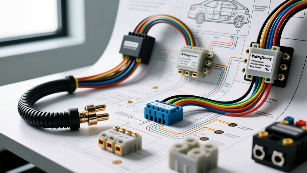
Entering the world of automotive electrical systems can feel like learning a new language. Whether you are installing a basic keyless entry system or a complex two-way remote starter, the schematic is your ultimate roadmap. For many DIY enthusiasts and junior installers, consulting a BulldogSecurity.com wiring diagram is the first step toward understanding how aftermarket modules interface with a vehicle's OEM (Original Equipment Manufacturer) harness. Modern vehicles are no longer simple 12-volt loops; they are rolling computer networks utilizing multiplexed data buses, CAN (Controller Area Network) protocols, and highly sensitive Body Control Modules (BCMs).
This beginner-friendly guide will demystify the fundamentals of automotive wiring diagrams. We will break down wire color codes, American Wire Gauge (AWG) sizing, relay logic, and the critical safety standards required to ensure your installation is both functional and safe. By mastering these fundamentals, you will transition from guessing wire functions to confidently executing precise, soldered connections that rival professional MECP (Mobile Electronics Certification Program) installations.
The Anatomy of an Aftermarket Wiring Diagram
When you first open a schematic, the web of color-coded lines and symbols can be overwhelming. However, every professional diagram follows a standardized logical flow. Power sources are typically drawn at the top or left, while grounds and outputs are routed to the bottom or right.
- Constant 12V+ (Battery): Usually represented by a thick red line, this circuit is live at all times and requires an inline fuse placed within 12 inches of the power source.
- Switched 12V+ (Ignition): Represented by yellow or orange lines, these circuits only receive power when the key is in the 'ON' or 'RUN' position.
- Ground (Chassis): Denoted by a black line terminating in a standard ground symbol (three descending horizontal lines). This must be tied to bare, unpainted metal, not an existing OEM ground wire which could cause backfeeding.
- Data Lines (CAN-H / CAN-L): Often twisted pair wires (e.g., Green and Green/White), these carry high-speed digital signals and require specialized splicing techniques to prevent network impedance errors.
Heavy-Gauge vs. Light-Gauge Harnesses
Aftermarket remote start modules typically separate their wiring into two distinct harnesses: the Heavy-Gauge (High-Current) harness and the Light-Gauge (Low-Current/Signal) harness. Understanding the difference is critical for selecting the correct wire taps and fuses. According to SAE International J1128 standards for low-tension primary cables, wire gauge dictates current-carrying capacity and voltage drop over distance.
| Wire Color | Function | Recommended AWG | Inline Fuse Rating |
|---|---|---|---|
| Red | 12V Constant Power | 10 AWG | 30A |
| Black | Chassis Ground | 10 AWG | N/A |
| Yellow | Ignition 1 (IGN) | 12 AWG | 20A |
| Pink | Starter (CRANK) | 12 AWG | 30A |
| Orange | Accessory (ACC) | 12 AWG | 15A |
| Brown | Parking Light Output | 18 AWG | 10A |
| Green | Door Trigger (-) | 18-22 AWG | 3A |
Understanding the 5-Pin Automotive Relay
A fundamental component you will encounter in any BulldogSecurity.com wiring diagram is the standard Bosch-style 5-pin relay. Relays act as electromagnetic switches, allowing a low-current signal (like a door pin switch or a remote start module output) to control a high-current circuit (like a starter motor or fuel pump).
Here is the standard pinout configuration you must memorize:
- Pin 30 (Common Input): High-current 12V+ input from the battery.
- Pin 87 (Normally Open - NO): High-current output. Receives power only when the relay coil is energized.
- Pin 87a (Normally Closed - NC): High-current output. Receives power when the relay is at rest. (Used for starter kill/fuel pump cut-off circuits).
- Pin 86 (Coil +): Low-current 12V+ trigger input.
- Pin 85 (Coil -): Low-current ground trigger. When 12V is applied to 86 and ground to 85, the electromagnetic coil pulls the internal switch from 87a to 87.
CAN Bus Integration and Bypass Modules
In vehicles manufactured after 2005, traditional hardwiring of ignition and starter wires is often replaced or supplemented by digital CAN bus interfaces. The BCM manages immobilizer transponder data, door locks, and tachometer signals over a two-wire network. When integrating an aftermarket bypass module, you will typically tap into the CAN-High (usually 2.5V to 3.5V) and CAN-Low (usually 1.5V to 2.5V) lines found at the OBD2 port or the main BCM connector.
Expert Tip: Never use standard 'Scotch-Lok' T-taps on CAN bus wires. The piercing mechanism damages the delicate twisted-pair shielding and alters the network's 120-ohm termination resistance, which can trigger cascading Check Engine Lights and transmission shifting errors. Always use Posi-Taps or carefully strip the insulation and solder the connection.
MECP Splicing Standards: Doing it Right
The Mobile Electronics Certification Program (MECP) strictly dictates that proper wire splicing is the cornerstone of a reliable installation. While electrical tape and twist-on wire connectors are common in household wiring, they are strictly forbidden in automotive environments due to extreme temperature fluctuations, moisture, and vibration.
The Solder and Heat-Shrink Method
- Strip exactly 1/2 inch of insulation from both the OEM and aftermarket wires.
- Slide a piece of adhesive-lined (dual-wall) marine heat shrink over one wire.
- Cross the exposed copper strands in an 'X' pattern and twist them tightly together.
- Apply rosin-core solder until the joint is shiny and fully penetrated (avoid acid-core solder, which causes corrosion).
- Slide the heat shrink over the joint and apply heat until the adhesive sealant oozes from both ends, creating a waterproof, vibration-proof bond.
Troubleshooting Decision Tree: The 'No-Crank' Condition
One of the most common issues beginners face when following a remote start diagram is a 'No-Crank' condition—the vehicle's lights flash, the fuel pump primes, but the starter motor does not engage. Use this diagnostic decision tree to isolate the fault:
- Step 1: Does the OEM key start the vehicle?
- No: The issue is with the vehicle's OEM starter, battery, or immobilizer, not the aftermarket module.
- Yes: Proceed to Step 2.
- Step 2: Do you hear a mechanical 'click' from the under-hood relay during remote start?
- No: The module is not sending the starter signal. Check the hood pin switch (if the hood is 'open', the module will disable the starter for safety).
- Yes: The module is sending the signal, but high-current power isn't reaching the starter solenoid. Proceed to Step 3.
- Step 3: Test the Pink Starter Wire at the module harness.
- Multimeter reads 0V during crank attempt: Internal module relay failure or blown 30A fuse on the heavy-gauge harness.
- Multimeter reads 12V during crank attempt: The fault lies between the module and the vehicle's starter wire. Check your T-tap connection, solder joints, and ensure you are testing the correct OEM starter wire (many modern cars use a starter relay in the fuse box rather than a direct wire to the solenoid).
Final Safety and Verification Protocols
Before reconnecting the vehicle's negative battery terminal, perform a comprehensive visual inspection. Ensure no bare copper is exposed, all inline fuses are properly seated and rated correctly, and the main control module is securely zip-tied above the kick panel, away from the parking brake pedal and HVAC blower motors. A secure, well-documented installation based on a thorough understanding of your schematic ensures years of reliable, safe operation. Always refer back to the specific vehicle year, make, and model wire guide provided by the manufacturer to account for mid-year production variations in OEM connector pinouts.