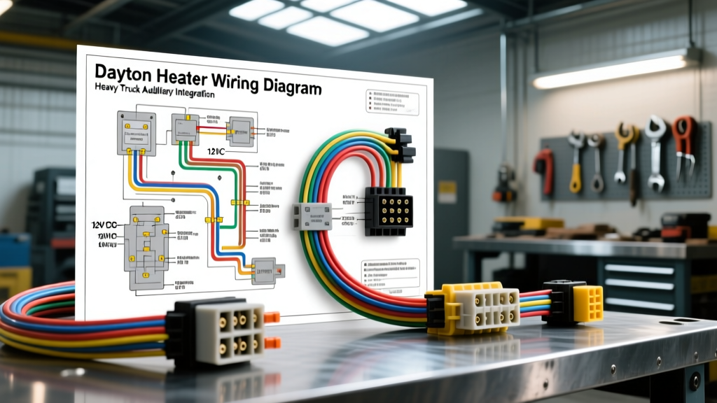
Dayton 12V DC Heaters in Commercial Fleet Applications
When outfitting heavy-duty commercial work trucks, service bodies, and auxiliary dog boxes, maintaining a stable ambient temperature is critical for both operator safety and the protection of sensitive diagnostic equipment. While standard automotive HVAC systems are designed for the primary cab, they rarely possess the ducting capacity or thermal output to heat expansive aluminum or steel utility beds. This is where integrating a Dayton 12V DC high-output utility heater becomes essential. However, unlike standard 120V AC residential units, deploying a Dayton DC heater in a Class 4 through Class 7 commercial vehicle requires a rigorous understanding of heavy-truck electrical architectures, continuous-duty amperage loads, and OEM upfitter switch integration.
This advanced technical deep dive explores the precise Dayton heater wiring diagram required to safely integrate these high-amperage 12V DC heating elements into a commercial truck's auxiliary electrical system. We will cover SAE-compliant wire sizing, ISO 280 relay pinouts, voltage drop calculations, and the specific OEM wire color codes required to route the trigger circuit through factory upfitter switch modules.
Core Electrical Specifications & Load Calculations
Before cutting a single wire, fleet electricians must calculate the exact continuous amperage draw of the Dayton 12V DC heater. Commercial truck charging systems typically operate between 12.8V (engine off, resting battery) and 14.4V (alternator actively charging). A standard Dayton 12V DC utility heater rated at 250 Watts will exhibit varying amperage draws depending on the system voltage at the time of operation.
Using Ohm's Law and the power equation (I = P / V), we can determine the maximum current draw:
- At 12.0V (Battery Depleted/Idling): 250W / 12.0V = 20.8 Amps
- At 14.4V (Alternator Charging): 250W / 14.4V = 17.3 Amps
Because the circuit must be engineered for the worst-case scenario (highest amperage draw at the lowest operational voltage), the wiring and overcurrent protection must be rated to handle a continuous load of at least 21 Amps. According to the National Electrical Code (NEC) and SAE continuous load guidelines, circuits operating for three hours or more must be derated by 125%. Therefore, 20.8A x 1.25 = 26 Amps. This dictates the minimum fuse size and wire gauge requirements to prevent thermal degradation of the insulation.
Table: Dayton 12V DC Heater Power Draw & SAE J1128 Wire Sizing
| Parameter | Specification / Requirement | Technical Notes |
|---|---|---|
| Heater Wattage | 250W Nominal | Dayton 12V DC Utility / Defroster Series |
| Max Continuous Current | 20.8 Amps (at 12.0V) | Calculated worst-case scenario |
| Overcurrent Protection | 30A MIDI or MAXI Fuse | Placed within 18 inches of the battery positive |
| Wire Gauge (0-15 ft run) | 10 AWG SAE J1128 | Stranded copper, 600V rated insulation |
| Wire Gauge (15-25 ft run) | 8 AWG SAE J1128 | Required to maintain <3% voltage drop |
| Relay Specification | ISO 280 Mini (30A/40A) | Bosch-style, continuous duty rated |
ISO 280 Relay Integration & Pinout Configuration
Running 21 Amps of continuous current through a standard dashboard toggle switch or an OEM upfitter switch will rapidly melt the switch contacts and damage the truck's body control module (BCM). The Dayton heater wiring diagram mandates the use of an ISO 280 mini relay to isolate the high-amperage load circuit from the low-amperage trigger circuit.
The ISO 280 relay utilizes a standardized 5-pin configuration. For this heavy-truck integration, the pins are wired as follows:
- Pin 30 (Common / Power In): Connected to the auxiliary battery positive terminal via the 30A MIDI fuse using 8 AWG red wire.
- Pin 87 (Normally Open / Load Out): Connected to the positive terminal of the Dayton heater using 8 AWG red wire.
- Pin 85 (Coil Ground): Connected to a verified, bare-metal chassis ground using 14 AWG black wire.
- Pin 86 (Coil Trigger): Connected to the OEM upfitter switch output using 14 AWG wire.
- Pin 87a (Normally Closed): Left unconnected and insulated with heat shrink tubing.
When the operator activates the upfitter switch, a low-current 12V signal is sent to Pin 86, energizing the electromagnetic coil. This pulls the internal contactor from Pin 87a to Pin 87, allowing the heavy 21A current to flow directly from the battery to the Dayton heater element and blower motor.
Routing Through OEM Upfitter Switches (Ford & Ram)
Modern heavy-duty trucks, such as the Ford F-450 Super Duty and Ram 4500/5500 chassis cabs, feature integrated upfitter switches designed specifically for auxiliary equipment like Dayton heaters. Tapping into these circuits requires precise knowledge of the OEM wire color codes to avoid back-feeding the BCM.
According to the Ford Motor Company Body Builder Advisory Service (BBAS), the auxiliary switch bank located in the overhead console provides pre-fused, battery-relayed power outputs. For a 250W Dayton heater drawing ~21 Amps, you must use one of the 30A rated switches.
- Ford Aux Switch 1 (30A): The trigger wire is typically Violet with a White tracer (VT/WH).
- Ford Aux Switch 2 (30A): The trigger wire is typically Brown with a White tracer (BN/WH).
To integrate the Dayton heater, locate the VT/WH wire under the driver's side kick panel or the designated upfitter pass-through grommet in the firewall. Splice into this wire using a Mil-Spec solder sleeve with heat shrink (do not use Scotchloks or T-taps, which cause galvanic corrosion and voltage drop). Route this 14 AWG trigger wire to Pin 86 of the ISO 280 relay mounted in the engine bay or under the service body sub-frame.
Chassis Grounding vs. Direct Battery Return
A frequent failure point in commercial truck upfitting is improper grounding of high-draw DC accessories. While it is tempting to ground the Dayton heater's negative lead to the nearest steel crossmember of the service body, this is a critical error. Service bodies are often mounted to the truck chassis using polyurethane isolation pucks to prevent galvanic corrosion and reduce NVH (Noise, Vibration, and Harshness). Furthermore, the steel beds are frequently powder-coated, creating a high-resistance dielectric barrier.
If the Dayton heater attempts to pull 21 Amps through a high-resistance chassis ground, the voltage will seek alternative paths, potentially back-feeding through the taillight harness or CAN-bus shielding, resulting in catastrophic BCM failure. The correct Dayton heater wiring diagram requires a dedicated 8 AWG ground return wire routed directly from the heater's negative terminal back to the auxiliary battery's negative post, or to a centralized, properly bonded copper busbar that is tied to the battery via a minimum 2/0 AWG ground cable.
Alternator Load Management & Dual-Battery Isolation
Integrating a continuous 21A load into a heavy truck's electrical system necessitates an audit of the vehicle's alternator capacity. A standard heavy-duty truck alternator outputs between 150A and 220A. However, the continuous DC load rule of thumb dictates that auxiliary loads should not exceed 50% of the alternator's rated output to prevent thermal failure of the internal diode bridge and stator windings.
If the truck is already running beacon lights, inverter/chargers, and HVAC blowers, adding the Dayton heater may overload the primary charging system. In these scenarios, the Dayton heater must be wired to a secondary auxiliary battery bank (e.g., dual AGM or LiFePO4 batteries) isolated by a continuous-duty solenoid, such as the Cole Hersee 24059. The solenoid ensures the Dayton heater only draws from the auxiliary bank when the ignition is in the 'Run' position, preventing the heater from draining the primary cranking batteries and leaving the fleet vehicle stranded.
Advanced Troubleshooting: Voltage Drop & Thermal Failure Modes
When a Dayton heater fails to produce adequate heat or the blower motor cycles erratically, the issue is rarely the heating element itself. As an automotive electrical expert, you must perform a dynamic voltage drop test across the entire circuit while the heater is under load.
- Set your multimeter to DC Volts.
- Place the red probe on the battery positive terminal and the black probe on the heater's positive input terminal. With the heater running, the reading should be less than 0.5V. A reading of 1.2V or higher indicates excessive resistance in the power wire, a corroded fuse holder, or failing relay contacts.
- Place the red probe on the heater's negative terminal and the black probe on the battery negative terminal. Again, the drop must be under 0.5V.
Additionally, Dayton 12V DC heaters are equipped with an internal bimetallic thermal cutoff switch, typically set to open at 120°C (248°F). If the blower motor bearings seize or the intake screen becomes clogged with job-site debris (drywall dust, sawdust), the element will overheat and trip the thermal cutoff. This switch is often non-resettable and requires the replacement of the internal thermal fuse link. Always inspect the blower motor amp draw; a healthy 12V blower motor should draw between 2A and 4A. A draw exceeding 6A indicates mechanical binding that will inevitably trip the thermal protection.