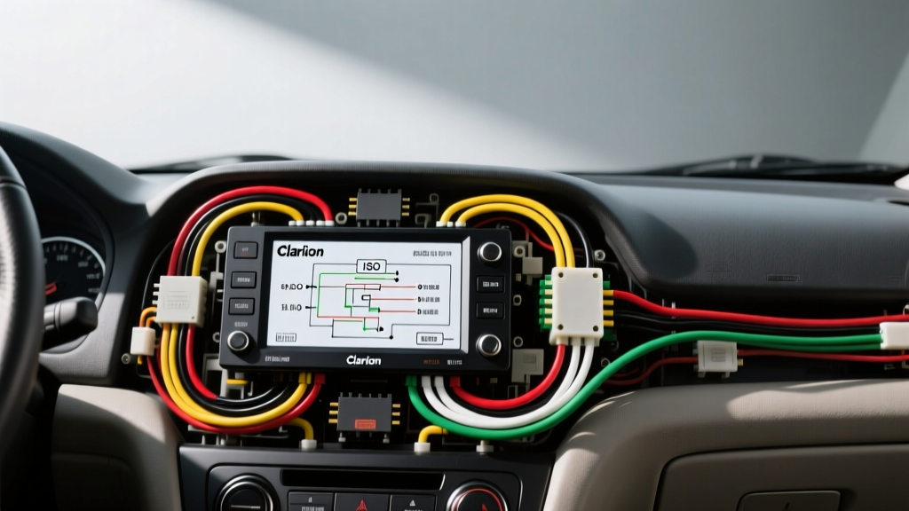
The Challenge of Clarion Head Unit Swaps in Custom Builds
Whether you are restomodding a classic muscle car, outfitting a marine vessel with a Clarion M505, or integrating a legacy Clarion CZ-series head unit into a modern daily driver, understanding the proprietary and standardized harness layouts is critical. Unlike factory OEM radios that rely on complex CAN-bus multiplexing, most aftermarket and marine Clarion units adhere to a universal standard, but interpreting the clarion radio wiring diagram code requires a solid grasp of automotive electrical principles. A misinterpreted pinout or an undersized power wire can lead to blown internal traces, memory loss, or catastrophic alternator whine.
This guide breaks down the exact wire color codes, AWG requirements, and connector pinouts necessary to execute a flawless Clarion head unit installation, complete with advanced modification strategies for vehicles lacking modern switched-power circuits.
Decoding the Standard Clarion Radio Wiring Diagram Code
Clarion utilizes the EIA/CEA RS-310 standard for its aftermarket and marine harness color codes. While the physical connector on the back of the chassis may be a proprietary 16-pin Molex-style block or a standard ISO 10487 dual-block, the pigtail harness translates these pins into universal color-coded wires.
Power and Ground Circuit Specifications
The most common failure point in custom Clarion installations is voltage drop on the memory circuit. Clarion head units utilize a dual-power architecture:
- Yellow Wire (Constant 12V / BATT): This powers the internal volatile memory (SRAM) for station presets and EQ settings. It draws a continuous standby current of 5mA to 15mA. Specification: Use a minimum of 16 AWG copper wire, fused within 12 inches of the battery positive terminal with a 10A ATC blade fuse.
- Red Wire (Switched 12V / ACC): This triggers the main power relay inside the head unit. It handles the initial inrush current to charge the internal capacitors. Specification: 16 AWG wire. Tapping into a low-current ignition source (like a cigarette lighter) can cause voltage sag during engine cranking, triggering the Clarion unit's internal low-voltage protection and causing reboot loops.
- Black Wire (Chassis Ground): Do not rely on the metal dash chassis for a high-fidelity ground. The Clarion internal MOS-FET amplifier (typically 4x50W peak) requires a clean, unpainted metal ground point. Specification: 14 AWG wire, terminated with a crimped and soldered ring terminal, secured with a star washer to bite through the zinc or e-coat on the vehicle's steel firewall.
ISO 10487 Block A Pinout Mapping
For European and modern global-market Clarion units utilizing the ISO 10487 standard, Block A handles the power distribution. Below is the exact pin-to-color mapping for the Clarion harness adapter:
| ISO Pin | Clarion Wire Color | Function | AWG Spec | Voltage / Signal Type |
|---|---|---|---|---|
| Pin 4 | Yellow | Constant Battery (Memory) | 16 AWG | +12V DC Continuous |
| Pin 7 | Red | Ignition Switched (ACC) | 16 AWG | +12V DC Switched |
| Pin 8 | Black | Chassis Ground | 14 AWG | 0V (Return Path) |
| Pin 5 | Blue / White Stripe | External Amp Turn-On | 18 AWG | +12V DC (Max 300mA) |
| Pin 6 | Orange / White Stripe | Illumination / Dimmer | 20 AWG | +12V DC or PWM |
Speaker Output Pinouts and Phase Matching
Clarion strictly follows the EIA speaker color code. When fabricating custom speaker pods or running new cabling through a roll cage, maintaining proper phase is critical for low-frequency response and soundstage imaging.
- Left Front: White (+) / White with Black Stripe (-)
- Right Front: Gray (+) / Gray with Black Stripe (-)
- Left Rear: Green (+) / Green with Black Stripe (-)
- Right Rear: Purple (+) / Purple with Black Stripe (-)
Technical Note: Clarion's internal amplifier uses a BTL (Bridge-Tied Load) output configuration. Never ground the negative speaker wires to the vehicle chassis. Doing so will short the internal output IC, instantly destroying the head unit's amplifier chip. Always run dedicated 18 AWG twisted-pair wiring directly from the Clarion harness to the voice coils.
Custom Modification: Adapting Clarion to Classic Vehicles
A frequent hurdle when installing a Clarion unit into a 1950s or 1960s classic vehicle is the absence of a dedicated, high-current 12V switched ignition (ACC) source. Vintage ignition switches are designed for low-amperage coil triggering and cannot safely handle the 5A to 8A inrush current of a modern head unit without risking a melted switch housing or electrical fire.
Bosch Relay Integration for Switched Power
To safely deliver switched power to the Clarion Red (ACC) wire, you must integrate a standard 30A Bosch-style SPST relay into the vehicle's wiring loom. This modification ensures the vintage ignition switch only carries the relay coil's minimal current draw (approx. 150mA), while the heavy lifting is handled by a direct battery feed.
- Relay Pin 86 (Coil +): Connect to a switched 12V source at the ignition switch or the wiper motor feed wire using 18 AWG wire.
- Relay Pin 85 (Coil -): Connect to a clean chassis ground using 18 AWG wire.
- Relay Pin 30 (Common Input): Run a dedicated 12 AWG wire directly to the battery positive terminal, protected by an inline 15A AGU fuse located within 6 inches of the battery.
- Relay Pin 87 (Normally Open Output): Run 16 AWG wire from this terminal directly to the Clarion harness Red (ACC) wire.
This topology guarantees a stable 14.4V supply during engine cranking and prevents the Clarion unit from experiencing brownouts when the starter motor engages.
Troubleshooting Illumination and CAN-Bus Conflicts
Modern vehicles (2005 and newer, particularly GM, Chrysler, and Ford) no longer use a simple 12V rheostat for dashboard illumination. Instead, the Body Control Module (BCM) sends a Pulse Width Modulated (PWM) square wave signal (typically 500Hz to 1kHz) to dim the dash lights.
If you connect the Clarion Orange/White illumination wire directly to a modern PWM dimmer circuit, the head unit's internal logic board will interpret the rapid voltage switching as a faulty power supply, resulting in severe LCD flickering or continuous rebooting. To resolve this during a custom install, you must install a PWM-to-DC low-pass filter module (such as the PAC DIM-1) or tap into a dedicated 12V parking light circuit that bypasses the BCM dimming logic entirely, sacrificing variable dimming for stable operation.
Eliminating Alternator Whine and Ground Loops
According to electromagnetic compatibility standards outlined by SAE International (SAE J1113), automotive audio systems are highly susceptible to Radiated and Conducted EMI. If your Clarion head unit emits a high-pitched whine that rises in pitch with engine RPM, you have a ground loop. This occurs when the Clarion head unit ground and the external amplifier ground are at different electrical potentials.
The Fix: Implement a 'Star Ground' topology. Run a dedicated 8 AWG ground wire from the Clarion head unit's Black wire, and a separate 4 AWG ground wire from your external amplifiers, to a single, centralized grounding block bolted directly to the vehicle's bare steel chassis. Do not daisy-chain grounds. Furthermore, ensure the RCA patch cables are routed down the opposite side of the vehicle's center console from the factory wiring harness and the Clarion power wires to prevent inductive coupling.
Authoritative References & Further Reading
For vehicle-specific OEM integration and advanced fabrication techniques, consult the following resources:
- Crutchfield Vehicle Wiring Database - Essential for identifying OEM CAN-bus data wires and factory amplifier integration protocols when retaining steering wheel controls with Clarion units.
- Clarion Marine Installation Manuals - Provides critical IPX-rating compliance data and conformal coating requirements for the M-Series harnesses in high-moisture environments.
- SAE International Automotive Electrical Standards - Reference for proper wire gauge ampacity ratings (SAE J1128) and EMI shielding techniques in high-noise alternator environments.