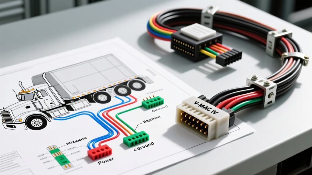
The Reality of Mack Truck Wiring Diagram Free Downloads
Finding a legitimate Mack truck wiring diagram free download is a common pursuit for independent diesel technicians and fleet mechanics. However, comprehensive OEM schematics for modern heavy-duty platforms—such as the Granite, Pinnacle, and Anthem series equipped with MP7 or MP8 engines—are proprietary. Full electrical routing diagrams are typically gated behind the Mack PACE (Premium Automated Customer Environment) portal or require a paid subscription to third-party heavy-duty service databases.
Despite this, the core architectural data for the Mack V-MAC IV (Vehicle Management and Control) Engine Management System and J1939 CAN bus topologies are standardized. Below is a technical specification reference detailing the critical pinouts, wire gauge requirements, and diagnostic parameters for the Mack MP8 engine harness, providing the essential data you would otherwise need a paid download to access.
Mack V-MAC IV 120-Pin EMS Connector Pinout Reference
The primary interface between the Mack MP8 engine sensors and the Engine Management System (EMS) module is the 120-pin OEM connector. This high-density connector is sealed to IP67 standards and utilizes specialized gold-plated terminals to prevent micro-fretting corrosion in high-vibration diesel environments. Below is a reference table for the most critical power, ground, and data circuits.
| Pin # | Circuit Function | Wire Color | AWG Size | Notes / Tolerances |
|---|---|---|---|---|
| 1 | Battery Positive (B+) | Red | 12 AWG | Continuous hot; fused at 30A |
| 2 | Chassis Ground | Black | 12 AWG | Must read < 0.05V drop under load |
| 3 | Switched Ignition | Yellow | 16 AWG | Hot in RUN/START; wakes EMS |
| 12 | J1939 CAN High | Blue | 20 AWG | Twisted pair with Pin 13 |
| 13 | J1939 CAN Low | Green | 20 AWG | Twisted pair with Pin 12 |
| 24 | Engine Speed/Timing (Cam) | White/Blue | 18 AWG | Shielded; Hall-effect signal |
| 45 | Injector 1 High Side | White/Black | 16 AWG | PWM driver circuit |
| 46 | Injector 1 Low Side | Black/White | 16 AWG | Return path to EMS driver |
| 88 | Boost Pressure Sensor Signal | Light Green | 20 AWG | 0.5V - 4.5V linear output |
J1939 Data Link Network Topology & Diagnostics
Modern Mack trucks rely heavily on the SAE J1939 Controller Area Network (CAN) bus to facilitate communication between the EMS, Transmission Control Module (TCM), Body Builder modules, and the instrument cluster. When chasing ghost faults or derate conditions, understanding the physical layer of this network is critical.
Termination Resistance Testing
The J1939 backbone requires exactly two 120-ohm terminating resistors located at the physical extremes of the network backbone. When the system is powered down and the batteries are disconnected, a multimeter placed across Pin 12 (CAN High) and Pin 13 (CAN Low) of the diagnostic connector (usually the 9-pin or 6-pin Deutsch diagnostic port) should read 60 ohms (± 5 ohms).
- 120 Ohms: Indicates one missing terminator (open circuit in the backbone or a disconnected module).
- Less than 55 Ohms: Indicates an extra terminator has been added to the network or a short between CAN H and CAN L.
- Infinite (OL): Complete break in the twisted pair harness or both terminators are missing.
With the key ON and network active, a DMM set to DC voltage will show CAN High oscillating between 2.5V and 3.5V (average ~2.6V), and CAN Low oscillating between 1.5V and 2.5V (average ~2.4V). Using an oscilloscope is highly recommended to visualize the dominant and recessive states and check for symmetrical voltage mirroring. For deeper analysis of heavy-duty network standards, refer to the SAE International J1939 documentation, which dictates the physical and data link layers for all Class 8 vehicles.
MP8 Fuel System & Injector Wiring Specifications
The Mack MP8 utilizes an Electronic Unit Injector (EUI) system (or High-Pressure Common Rail on later EPA 2021+ variants). The V-MAC IV module fires the injector solenoids using high-current Pulse Width Modulation (PWM). Because these circuits carry significant amperage spikes, the wiring harness is highly susceptible to chafing against the valve cover or cylinder head.
Injector Solenoid Resistance Values
When diagnosing a misfire or an inactive injector fault code (e.g., SPN 651-FMI 5 for current below normal), perform a static resistance test at the valve cover harness connector.
- Expected Resistance: 0.5 Ω to 1.2 Ω at 68°F (20°C).
- Insulation Resistance (Megger Test): Must exceed 10 MΩ between either injector pin and engine block ground. Warning: Disconnect the EMS module before performing a Megger test to prevent catastrophic ECU damage.
Sensor Reference Voltage & Signal Verification
Analog sensors on the Mack MP8, such as the Boost Pressure, Oil Pressure, and Fuel Rail Pressure sensors, operate on a standard 5-Volt Reference (VREF) circuit. A short to ground on any single 5V reference leg can pull the entire V-MAC IV VREF plane down, causing a cascade of seemingly unrelated fault codes.
Testing the 5V VREF Plane
- Set your Digital Multimeter (DMM) to DC Volts.
- Back-probe the 5V reference wire (typically Red or Pink depending on the specific sensor harness branch) at the Boost Pressure Sensor connector.
- Key ON, Engine OFF (KOEO). The reading must be 4.95V to 5.05V.
- If voltage reads 0.0V - 2.5V, unplug sensors one by one (Oil Pressure, Fuel Pressure, EGR Delta P) until the 5V reference snaps back to 5.0V. The sensor that, when unplugged, restores the voltage contains an internal short.
For official service procedures and wiring schematic access, fleet managers should consult the Mack Trucks Service Support portal to set up authorized PACE access.
Heavy-Duty Harness Repair Standards
Field repairs on Mack engine harnesses must withstand extreme thermal cycling (up to 150°C near the turbocharger) and high-frequency vibration. Standard electrical tape and twist-on connectors are strictly prohibited by OEM standards.
- Splicing: Use only adhesive-lined, solder-seal heat shrink tubing (e.g., Raychem SCL or equivalent). The internal solder ring must melt and flow around the wire strands, while the outer polyolefin layer shrinks to form an IP67 waterproof seal.
- Terminal Replacement: When replacing pins in the 120-pin EMS connector or TE Connectivity / Deutsch DT series connectors, always use the manufacturer-specified ratcheting crimp tool. A proper crimp will pass a 15 lb pull-test without the wire slipping from the terminal barrel.
- Loom Protection: Replace any damaged split-loom with high-temperature nylon braided sleeving or corrugated polyamide tubing, securing it with friction tape (Tesa 51036) rather than zip-ties, which can cut into the harness over time.
- Connector Torque: When mating the 120-pin EMS connector, ensure the locking lever is fully engaged and the retaining bolt (if equipped on the specific V-MAC IV variant) is torqued to 4-6 Nm to maintain the environmental seal without cracking the polymer housing.