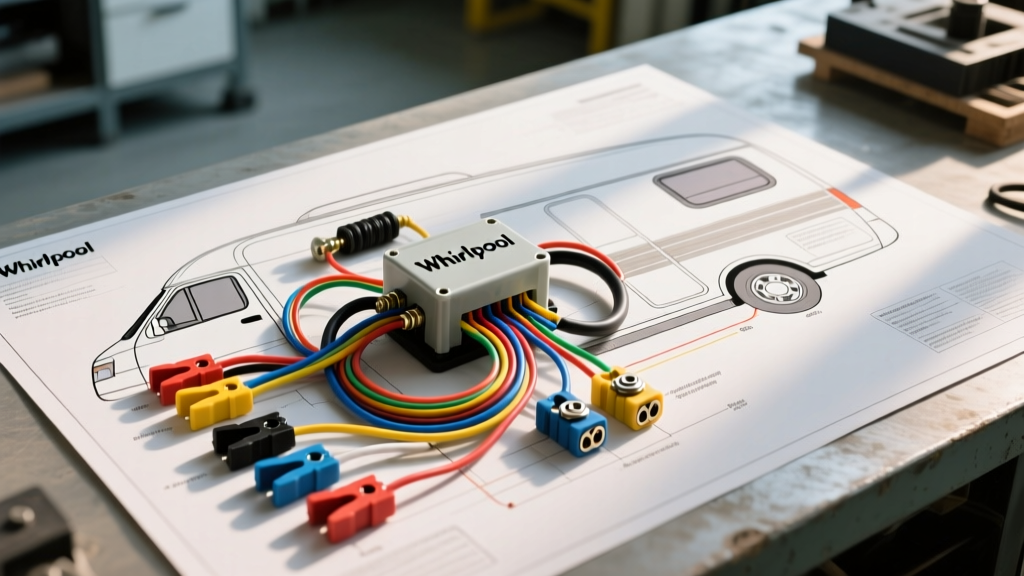
Integrating Residential Appliances in Motorhome Electrical Systems
When outfitting a Class A diesel pusher, a custom expedition vehicle, or a luxury fifth-wheel toy hauler with residential appliances, the laundry center presents the most severe electrical bottleneck in the entire chassis. Specifically, the 240V AC heating circuit demands up to 5,500 watts of continuous power, requiring meticulous planning across both the RV’s high-current DC/AC distribution network and the appliance's internal safety loops. As an automotive and RV electrical specialist, I frequently consult the wiring diagram for Whirlpool dryer heating element assemblies to troubleshoot no-heat conditions. These failures often stem from either internal appliance component degradation or upstream inverter and transfer switch voltage drops caused by vehicular vibration and undersized cabling.
Decoding the Wiring Diagram for Whirlpool Dryer Heating Element
Unlike automotive 12V DC resistive heaters or PTC ceramic elements, the Whirlpool residential dryer relies on a 240V split-phase AC supply. The heating element (typically Whirlpool part number WP8544771) is a coiled nichrome wire assembly housed in a stamped steel enclosure, rated at 5,200W to 5,500W. When analyzing the wiring diagram for Whirlpool dryer heating element circuits, you must trace the series-loop safety architecture designed to prevent thermal runaway and chassis fires.
The circuit path begins at the rear terminal block where L1 (120V) and L2 (120V) enter the dryer cabinet. L2 feeds directly through a high-temperature wire to one side of the heating element. L1, however, is routed through a complex series of thermal switches and the drive motor’s centrifugal switch before it reaches the element.
- Thermal Fuse (WP3392519): Located on the blower housing exhaust path, this non-resettable fuse opens at 250°F (121°C). It is the primary fire-prevention device.
- High-Limit Thermostat (WP3977767): Mounted directly on the heater box, it breaks the circuit at 250°F but resets upon cooling to prevent localized overheating.
- Cycling Thermostat (WP3387134): Regulates the internal drum temperature by cycling the L1 feed on and off based on user-selected heat settings.
- Motor Centrifugal Switch: A critical safety interlock located inside the drive motor assembly. The switch only closes to complete the L1 heater circuit when the motor reaches operating RPM, ensuring the blower is actively moving air before the nichrome element energizes.
Internal Wire Color Codes and Terminal Pinouts
Inside the Whirlpool cabinet, the wiring harness utilizes high-temperature fiberglass or Teflon-insulated conductors to withstand the ambient heat of the drying chamber. Standard automotive PVC-insulated wire (like GXL or TXL) will melt and short out in this environment.
| Component Path | Terminal Designation | Wire Color | AWG / Insulation Type |
|---|---|---|---|
| Terminal Block to Timer/Control Board | L1 Input | Black | 10 AWG THHN / Nylon |
| Terminal Block to Element Assembly | L2 Input | Red | 10 AWG THHN / Nylon |
| Cycling Thermostat to Element | Element Terminal 1 | Red w/ White Stripe | 14 AWG Fiberglass Braid |
| Thermal Fuse to Motor Switch | Motor Switch Pin 2 | White | 14 AWG Fiberglass Braid |
RV Power Distribution: Sizing the Inverter and DC Feed
If you are running this Whirlpool dryer off-grid via a solar array and lithium battery bank, you cannot use a standard 12V DC to 120V AC inverter. You must utilize a 48V DC architecture with stacked or split-phase inverters (such as dual Victron MultiPlus-II 48/5000 units synced via a master/slave data cable) to generate the required 240V AC split-phase output.
According to RVIA (Recreation Vehicle Industry Association) standards and NEC Article 551, the DC wiring between the battery bank and the inverter must account for the massive amperage draw. A 5,500W heating element pulling from a 48V nominal battery bank will draw approximately 125 Amps DC continuously, factoring in inverter efficiency losses and low-voltage sag.
| System Segment | Wire Gauge | Standard / Spec | Termination & Torque |
|---|---|---|---|
| Battery Bank to Busbar | 4/0 AWG | SAE J1128 / Class K Copper | 3/8" Lug, 12 ft-lbs |
| Busbar to Inverter DC Input | 4/0 AWG | UL 1283 (Battery Cable) | 5/16" Bolt, 10 ft-lbs |
| Inverter AC Out to Receptacle | 10 AWG | NM-B or THHN in conduit | NEMA 14-30R, 14 in-lbs |
| Dryer Terminal Block Screws | N/A | OEM Specification | 25 in-lbs (Critical) |
Always use adhesive-lined marine-grade heat shrink (3:1 ratio) over hydraulic crimps to prevent oxidation and strand fracturing from vehicular road vibration. Furthermore, ensure the dryer's terminal block screws are torqued exactly to spec; loose terminal connections are the number one cause of localized melting and electrical fires in RV laundry installations.
Wire Routing and EMI Shielding in Automotive Chassis
When routing the 4/0 AWG DC cables and the 10 AWG 240V AC lines through a motorhome chassis or fifth-wheel underbelly, electromagnetic interference (EMI) and physical abrasion are major concerns. The high-current DC surge required to initiate the heating element can induce voltage spikes in adjacent low-voltage CAN bus networks or sensor wiring. Maintain a minimum physical separation of 6 inches between high-voltage AC/DC lines and sensitive automotive data lines. Where crossing is unavoidable, route the cables at strict 90-degree angles. All wiring passing through sheet metal bulkheads must be protected by rubber grommets or split loom tubing to prevent insulation chafing from chassis torsion.
Diagnostic Decision Tree: No-Heat Condition
When the dryer tumbles but produces no heat, technicians must determine if the fault lies within the Whirlpool's internal safety loop or the RV's upstream power delivery. Use this diagnostic sequence with a CAT III multimeter:
- Verify Split-Phase Voltage: Measure across L1 and L2 at the dryer's terminal block. You must read 240V AC (+/- 5%). If you read 120V, an inverter synchronization fault, a blown high-speed fuse, or a tripped double-pole breaker in the RV's AC distribution panel is starving the element. Use the Low-Z (impedance) setting on your multimeter to eliminate ghost voltage readings common on inverter outputs.
- Test the Thermal Fuse: Disconnect shore and battery power. Remove the back panel and locate the thermal fuse on the blower housing. Perform a continuity test. An open circuit (OL) indicates a blown fuse, usually caused by restricted exhaust venting in the RV's exterior sidewall cap or a clogged lint screen.
- Verify the Centrifugal Switch: If the thermal fuse and thermostats show continuity, the issue is often the motor switch. With the dryer running, measure AC voltage between the motor switch heater terminal and L2. If you have 240V here but the element isn't heating, the internal switch contacts are pitted or fused open, requiring a drive motor replacement.
- Measure Element Resistance: Disconnect the element wires. Measure resistance across the two element terminals. A healthy Whirlpool 5,500W element will read between 9 and 11 Ohms. A reading of OL means the nichrome coil has fractured internally.
Common Failure Modes in Motorhome Installations
The most frequent cause of premature heating element failure in RV installations is voltage sag caused by undersized DC battery cables or degraded busbar connections. When the 48V DC input drops below the inverter's low-voltage cutoff during the initial heating surge, the inverter rapidly cycles on and off. This rapid cycling induces severe thermal shock to the nichrome heating coils, causing them to become brittle and snap. To prevent this, ensure your battery bank possesses adequate Amp-Hour (Ah) capacity to sustain high-load DC draws, and adhere strictly to SAE J1128 guidelines for low-tension primary cable routing.
Furthermore, verify that the RV's exterior dryer vent flap opens fully. Aerodynamic drag from driving at highway speeds can sometimes force poorly designed vent flaps shut or deform the ducting, triggering the high-limit thermostat and eventually blowing the thermal fuse. Upgrading to a rigid, aerodynamic RV dryer vent cover is highly recommended for frequent travelers.