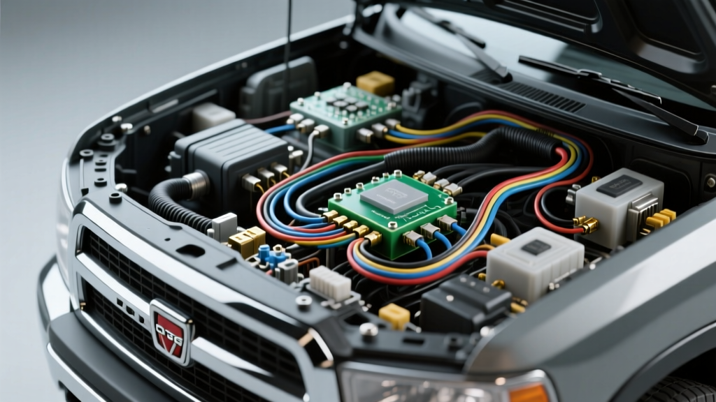
The Hidden Dangers of Misinterpreting Dodge Truck Wiring Diagrams
When troubleshooting a 5.9L Cummins diesel or a 5.7L HEMI V8, relying on accurate Dodge truck wiring diagrams is mandatory. However, Mopar electrical architecture differs significantly from Ford or GM platforms. Misinterpreting these schematics leads to catastrophic failures, including fried Totally Integrated Power Modules (TIPM), shorted Next Generation Controller (NGC) PCMs, and compromised airbag clock springs. Many technicians and DIYers assume that a wiring diagram is a universal map, but Mopar utilizes proprietary color codes, multiplexed network topologies, and specific grounding planes that require specialized knowledge. This guide outlines the most critical safety warnings and common mistakes made when reading and applying Dodge truck schematics.
Mistake 1: Misreading Mopar Two-Letter Color Codes
One of the fastest ways to short a 5-volt reference circuit to a 12-volt battery feed is by misinterpreting Mopar wire color codes. Unlike aftermarket wiring that spells out colors, Dodge truck wiring diagrams use a strict two-letter abbreviation system. Furthermore, Mopar uses 'tracer' colors to denote secondary stripes, represented by a slash (e.g., DB/YL means Dark Blue with a Yellow tracer).
Common Color Code Misinterpretations
- GR vs. GY: Assuming 'GR' means Green. In Mopar schematics, 'GR' is not standard; Green is 'GN' or 'DG' (Dark Green). 'GY' is Gray. Confusing a Gray ground wire for a Green signal wire can instantly fry a sensor.
- DB vs. DG: Dark Blue (DB) and Dark Green (DG) look similar in faded diagrams. Dark Blue is often used for PCI bus or CAN networks, while Dark Green is frequently used for 12V accessory feeds.
- OR vs. RD: Orange (OR) and Red (RD) are both used for high-current battery feeds, but Orange is typically fused ignition-switched power (like the ASD relay feed), while Red is often constant battery power.
| Mopar Code | Base Color | Typical Dodge Application |
|---|---|---|
| BK | Black | Primary Chassis Ground |
| WT | White | High Beam / Headlight Feed |
| DG | Dark Green | Fused Ignition Run/Start (ASD) |
| VT | Violet | PCI Bus / Multiplexed Data |
| YL | Yellow | ABS Module / Airbag Signals |
| TN | Tan | Instrument Cluster / Gauge Signals |
Reference: Always verify physical wire colors against the schematic legend, as UV exposure can fade Dark Green (DG) to look like Black (BK) in older Ram engine bays.
Mistake 2: Probing Multiplexed Networks with Test Lights
Modern Dodge trucks rely heavily on multiplexed networks to communicate between the PCM, TIPM, and Body Control Module (BCM). Older models (1998-2003) utilize the PCI (Programmable Communications Interface) bus, while newer models (2004-present) use CAN C (High Speed) and CAN IHS (Interior High Speed) networks.
The PCI Bus Backfeed Danger
The PCI bus is a single-wire network (typically Violet/White) operating at roughly 78 kbps. A critical safety warning: never use a standard incandescent test light on a PCI bus circuit. The test light draws too much current, pulling the bus voltage down and potentially backfeeding 12V into the delicate transceiver chips inside the BCM or PCM. Always use a high-impedance digital multimeter (DMM) or a dedicated logic probe when diagnosing PCI circuits.
CAN C and CAN IHS Diagnostic Safety
CAN C operates at 500 kbps and utilizes a twisted pair of wires (CAN H+ and CAN L-). Probing these wires at the OBD-II Data Link Connector (DLC) requires strict adherence to SAE J1962 Diagnostic Connector Standards. Piercing the insulation of CAN C wires with a standard T-pin can cause the twisted pair to short together, taking down the entire powertrain network and causing a no-start condition.
| OBD-II DLC Pin | Circuit Function | Mopar Wire Color | Safe Testing Tool |
|---|---|---|---|
| Pin 6 | CAN C High (+) | White / Dark Green | High-Impedance DMM / Breakout Box |
| Pin 14 | CAN C Low (-) | White / Orange | High-Impedance DMM / Breakout Box |
| Pin 4 | Chassis Ground | Black | Test Light / DMM |
| Pin 5 | Signal Ground | Black / Light Green | High-Impedance DMM Only |
Mistake 3: Bypassing TIPM Internal Relays Incorrectly
The Totally Integrated Power Module (TIPM) on 2006-2012 Ram trucks is notorious for internal solder joint failures, particularly in the fuel pump and Automatic Shutdown (ASD) relay circuits. When the internal relay fails, many owners attempt a 'TIPM bypass' by hardwiring an external relay. This is where severe safety hazards arise.
Wire Gauge and Fusing Errors
The fuel pump circuit on a 5.7L HEMI requires significant current, especially under heavy load or when towing. A common mistake is using 16 AWG or 18 AWG wire for the bypass jumper. According to SAE J1128 Primary Cable Specifications, 16 AWG wire in a high-temperature engine bay environment is only rated for roughly 10 amps. The fuel pump can draw 12-15 amps on startup. Using undersized wire causes severe voltage drop, overheating, and potential engine bay fires.
- Correct AWG Sizing: Always use a minimum of 12 AWG primary automotive wire (GXL or TXL type) for fuel pump and ASD relay bypasses.
- Inline Fusing: You MUST install a 20A ATC inline fuse within 6 inches of the battery positive terminal connection point. Do not rely on the TIPM's main fuse to protect your aftermarket jumper wire.
- Connection Integrity: Never use 'T-taps' or 'Scotch locks' on the TIPM harness. These connectors sever wire strands and invite moisture. Use Mopar Wiring Repair Kits and Pigtail Specifications to properly crimp and heat-shrink splices.
Mistake 4: Ignoring PCM Ground Topology
Mopar NGC (Next Generation Controller) PCMs and Cummins ECMs utilize dedicated, isolated ground planes for sensor signals. A frequent mistake when reading Dodge truck wiring diagrams is assuming that any clean chassis bolt is a suitable ground for a sensor shield or an aftermarket data logger.
Ground Loops and Sensor Noise
The MAP (Manifold Absolute Pressure) and TPS (Throttle Position Sensor) rely on a clean 5V reference and a dedicated signal ground back to the PCM. If you ground an aftermarket wideband O2 controller or a sensor shield to the battery negative terminal instead of the designated PCM ground pin (e.g., Pin 32 on the C1 38-way connector), you create a ground loop. The voltage potential difference between the battery negative and the PCM internal ground plane can introduce millivolt fluctuations, causing erratic shifting, rough idle, and false misfire codes.
- Locate the Dedicated Ground Node: Refer to the wiring diagram's ground distribution chart. Look for ground nodes labeled 'G101' or 'G102' near the cylinder heads.
- Clean to Bare Metal: Remove the ground bolt, clean the eyelet and the casting with a wire brush, and apply a dielectric grease to the threads to prevent galvanic corrosion.
- Torque to Spec: M8 ground bolts on the engine block must be torqued to 20 Nm (15 lb-ft) to ensure consistent electrical resistance under thermal expansion.
Pre-Work Safety Protocol Checklist
Before cutting, splicing, or probing any wire on a Dodge truck, complete this mandatory safety checklist:
- Disconnect the Battery: Always disconnect the negative battery terminal and wait 3 minutes before working near the TIPM or airbag modules to allow the capacitors to discharge.
- Verify the Diagram Year and Trim: A 2008 Ram 2500 with a 6.7L Cummins has entirely different injector harness routing and pinouts than a 2008 Ram 1500 with a 4.7L V8. Ensure your schematic matches the exact 8th digit of the VIN.
- Use Proper Crimp Tools: For any Deutsch connectors or Mopar Metri-Pack terminals, use the correct ratcheting crimp tool. Soldering is strictly prohibited in modern Mopar repair procedures due to the wicking of solder into the wire insulation, which causes brittle wires and breaks in high-vibration environments.
By respecting the unique architecture of Mopar electrical systems and adhering to these safety warnings, you can effectively utilize Dodge truck wiring diagrams to diagnose complex issues without risking thousands of dollars in collateral module damage.