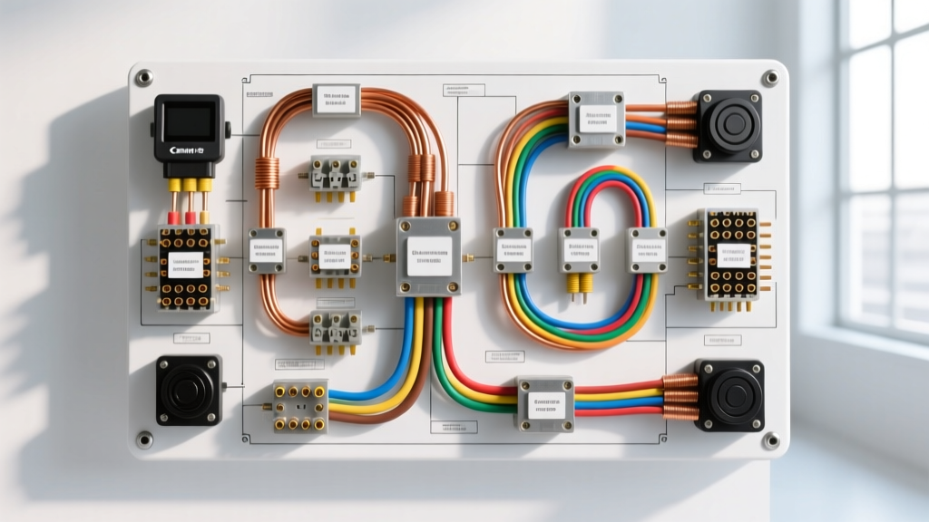
The Problem with a Generic Lift Control Panel Wiring Diagram PDF Free Download
When automotive technicians, mobility fleet managers, and owner-operators search for a lift control panel wiring diagram PDF free download, they are usually facing a critical downtime scenario. Whether you are repairing a wheelchair accessibility lift on a transit van or troubleshooting a commercial truck tail lift, relying on generic, unverified PDF schematics found on forums is a massive risk. Modern automotive lift systems have transitioned from simple analog relay logic to complex CAN-bus multiplexing and PWM (Pulse Width Modulation) motor controllers. A diagram from a 2012 system will not match the pinouts of a current-generation multiplexed control panel, leading to shorted ECU gates or fried solid-state contactors.
Instead of hunting for outdated PDFs, this guide serves as a comprehensive product comparison and selection reference. We break down the wiring architectures of the industry's top lift control systems, provide exact pinout configurations, and detail the AWG specifications required for safe, reliable operation.
Product Comparison: Top Automotive Lift Control Systems
Selecting the right replacement control panel or building a custom harness requires understanding how different manufacturers handle high-amperage motor loads and low-voltage logic signals.
1. BraunAbility Century UVL (Under Vehicle Lift)
Braun UVL systems are the gold standard for wheelchair accessible vans. The control panel utilizes a ruggedized 6-pin or 8-pin Weather-Pack connector. Older models use direct analog switching to trigger heavy-duty Bosch-style relays, while newer UVL2000 series panels use a proprietary logic board that communicates with a centralized power module. The main power feed requires 2 AWG GXL wire to handle the 120A+ inrush current of the hydraulic pump motor, while the control panel harness uses 18 AWG TXL for signal wires.
2. Ricon Split-Panel & Clear-Away Series
Ricon systems frequently employ a 14-pin Ampseal connector for their control interfaces. The defining feature of modern Ricon panels is the integration of CAN-bus communication between the outboard control panel and the main power node. This means the panel does not carry high current; it only sends digital data packets. Attempting to wire a Ricon CAN-bus panel using an analog 12V trigger diagram will instantly destroy the panel's internal transceiver. Proper termination requires a 120-ohm resistor across the CAN-High and CAN-Low lines.
3. Tommy Gate Commercial Truck Tail Lifts
Tommy Gate systems often use a simpler, highly robust 5-pin DIN connector or a 4-pin toggle switch setup for commercial box trucks. Because these lifts operate in harsh, high-vibration environments, the control panels are entirely sealed and rely on heavy-duty magnetic contactors rather than PCB-mounted relays. The wiring relies heavily on 10 AWG to 6 AWG power wires routed directly to the contactors, with the control panel handling only the 5A coil-trigger circuits.
Master Control Panel Pinout & Wire Color Specification Chart
Below is a standardized reference table for a typical 8-pin analog lift control panel interface (commonly found in Braun and generic transit van lifts). Always verify against the manufacturer's specific harness tag before applying power.
| Pin Number | Function | Wire Color (OEM Standard) | Wire Gauge (AWG) | Voltage / Signal Type |
|---|---|---|---|---|
| Pin 1 | Main Logic Power (Ignition) | Red | 16 AWG | 12V DC (Switched) |
| Pin 2 | System Ground | Black | 14 AWG | Ground (Chassis) |
| Pin 3 | Deploy / Lower Command | Yellow | 18 AWG | 12V DC Trigger (Max 2A) |
| Pin 4 | Stow / Raise Command | Green | 18 AWG | 12V DC Trigger (Max 2A) |
| Pin 5 | Door Interlock Status | White | 18 AWG | Ground Switch (Closed when door open) |
| Pin 6 | Platform Fold/Unfold | Blue | 18 AWG | 12V DC Trigger |
| Pin 7 | LED Illumination Power | Brown | 20 AWG | 12V DC (Headlight circuit) |
| Pin 8 | Fault / Diagnostic Output | Orange | 20 AWG | Open Collector (Pulls to Ground on fault) |
Selecting the Right Wiring Harness & Relay Upgrades
When replacing a damaged harness or upgrading a lift control panel, wire selection and relay sizing are critical. According to SAE J1128 standards for low-tension primary cables, you must account for the ambient temperature under the vehicle chassis. Standard PVC wire will melt or degrade near the exhaust or hydraulic pump. Always specify Cross-Linked Polyethylene (XLPE) insulated wire, such as GXL or TXL, which withstands temperatures up to 125°C (257°F).
Relay Selection for High-Current Lift Motors
Standard 30A automotive relays are insufficient for the main hydraulic pump circuits of accessibility and tail lifts. The control panel triggers these relays, but the relays themselves must be rated for the motor's inrush current.
- Bosch JD1912 Style (40A/50A): Suitable only for platform fold/unfold motors and lighting circuits.
- Heavy-Duty Solenoids (150A Continuous): Required for the main lift/lower hydraulic pump. Must feature copper contact points and a built-in arc suppression diode to prevent frying the control panel's logic board when the coil de-energizes.
- Solid-State Contactors (SSC): The modern upgrade. SSCs use MOSFETs to switch high current with zero moving parts, eliminating contact pitting and reducing voltage drop to less than 0.1V.
Troubleshooting Control Panel Communication Failures
Use this diagnostic decision tree when a lift control panel is completely unresponsive or throwing erratic fault codes.
Symptom: Panel LEDs are dead, no motor response.
- Check Main Power Feed: Measure voltage at the 150A ANL fuse near the battery. If 12V is present, move to the control module.
- Inspect the Interlock Circuit: Most OEM systems (like Braun and Ricon) wire the control panel through a door jamb switch. If the door switch is misaligned, the panel ground path is broken. Bypass the door switch temporarily to test.
- Test for Voltage Drop: Place your multimeter probes on the battery positive terminal and the Pin 1 (Logic Power) wire at the back of the control panel connector. A reading greater than 0.2V indicates severe corrosion in the harness or a failing ignition relay.
Symptom: Panel lights up, but buttons do not trigger the motor (CAN-Bus Systems).
- Verify Termination Resistance: Disconnect the battery. Set your multimeter to Ohms. Measure across Pin 3 (CAN-H) and Pin 4 (CAN-L) on the main module harness. You should read exactly 60 ohms (two 120-ohm resistors in parallel). If you read 120 ohms, one of the network termination resistors is missing or blown.
- Check for Short to Ground: Measure resistance between CAN-H and Chassis Ground. It should read infinite (OL). Any continuity means the harness has rubbed through against the steel chassis, shorting the data line.
Authoritative References & OEM Documentation
For exact, year-specific schematics, always bypass third-party PDF repositories and consult the manufacturer's direct engineering resources. You can find verified installation manuals, wiring schematics, and diagnostic flowcharts through the following official channels:
- BraunAbility Technical Support: Access the official dealer portal and service manuals at BraunAbility Support for UVL and Entervan wiring schematics.
- Tommy Gate Installation Guides: Download verified commercial tail lift wiring diagrams and hydraulic routing charts from the Tommy Gate Manual Repository.
- SAE International: Review the SAE J1128 Standard for exact wire gauge ampacity derating curves in high-temperature automotive environments.
By understanding the underlying architecture of your specific lift system and utilizing the correct AWG and connector standards, you can eliminate the need for unreliable internet searches and ensure your vehicle's lift system operates safely for years to come.