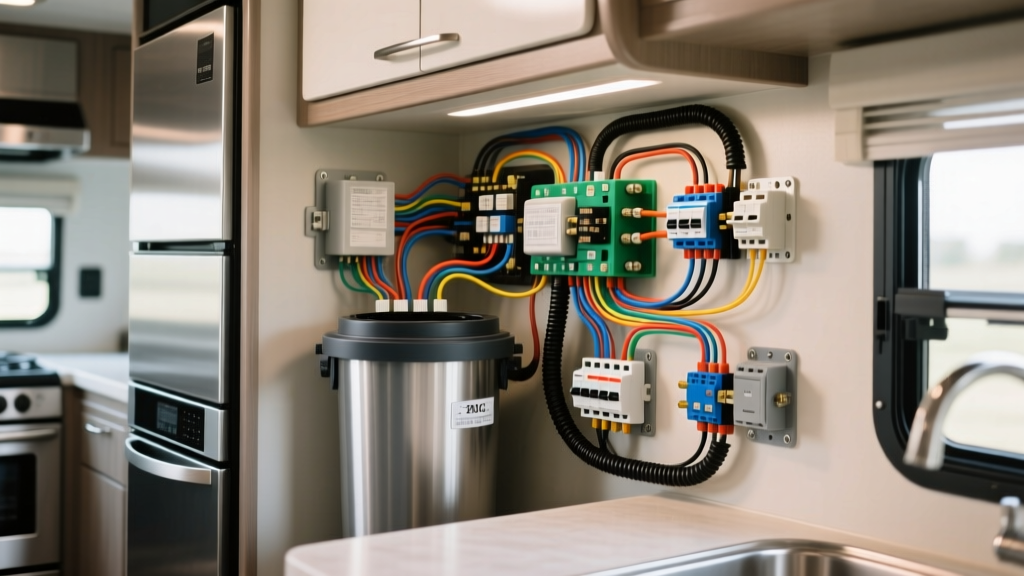
Introduction to RV Dual-Voltage Galley Systems
Integrating a high-draw appliance into a motorhome or fifth-wheel RV requires a deep understanding of dual-voltage electrical architectures. When technicians and DIYers search for a standard wiring diagram for garbage disposal units, they are typically met with residential 120V AC schematics. However, applying a standard residential diagram to an RV galley is a critical error that can lead to inverter failure, catastrophic battery bank voltage sag, or electrical fires. In an automotive or RV environment, the coach (living space) and chassis (engine/drivetrain) electrical systems must remain carefully isolated while still communicating for safety interlocks.
A motorhome garbage disposal requires a 120V AC motor circuit to handle the grinding load, paired with a 12V DC control circuit to operate the switch and relay. More importantly, it requires an Automatic Transfer Switch (ATS) interlock to ensure the disposal can only be activated when the RV is connected to shore power or running the onboard generator. This prevents the 1500W+ startup surge from drawing down the 12V DC coach batteries through the inverter, which would instantly trip the inverter's low-voltage cutoff and potentially damage the battery cells.
Component and Wire Gauge Specification Matrix
The following table outlines the exact wire gauges, insulation types, and color codes required for a safe, RVIA-compliant installation. All 120V AC wiring must be copper, and all 12V DC wiring must be stranded automotive-grade copper.
| Circuit Segment | Voltage | AWG Size | Wire Type | Color Code |
|---|---|---|---|---|
| Main AC Hot (Panel to Contactor) | 120V AC | 12 AWG | THHN / Romex 12/2 | Black |
| Main AC Neutral | 120V AC | 12 AWG | THHN / Romex 12/2 | White |
| AC Equipment Ground | 120V AC | 12 AWG | THHN / Bare Copper | Green / Bare |
| DC Coil Power (Fuse to Switch) | 12V DC | 14 AWG | SAE J1128 Stranded | Red |
| DC Switch Leg (Switch to Relay) | 12V DC | 14 AWG | SAE J1128 Stranded | Blue |
| DC Interlock Signal (ATS to Relay) | 12V DC | 16 AWG | SAE J1128 Stranded | Yellow |
| DC Ground (Relay to Chassis) | 12V DC | 14 AWG | SAE J1128 Stranded | White (RVIA Std) |
120V AC Main Power Circuit Walkthrough
The 120V AC side of the circuit begins at the RV's main AC distribution panel. According to NFPA 70 (National Electrical Code) Article 551, which governs recreational vehicles, all 120V receptacles and hardwired appliances within 6 feet of the galley sink must be protected by a Ground Fault Circuit Interrupter (GFCI). Therefore, the disposal must be wired to a dedicated 20A GFCI breaker.
From the 20A breaker, a 12 AWG Black (Hot) and 12 AWG White (Neutral) wire is routed through the RV's underbelly or cabinetry chase to a heavy-duty isolation contactor mounted near the disposal. We do not wire the disposal directly to a standard wall switch because standard 15A residential switches are not rated for the inductive startup surge of a disposal motor in a high-vibration automotive environment. Instead, the 120V AC Hot wire terminates on the Line (L1) terminal of the contactor. The Load (T1) terminal of the contactor then feeds the disposal's internal junction box. The 12 AWG Green ground wire bypasses the contactor entirely, running continuously from the panel's ground bus directly to the disposal's chassis grounding screw to ensure a fault path is always present.
12V DC Control Circuit and Inverter Interlock
The 12V DC control circuit is where the automotive electrical expertise truly comes into play. To prevent the disposal from operating on inverter power, we utilize a 12V DC coil contactor (such as a White-Rodgers 586-902 or an RV-specific Trompeter isolation relay) that features 120V AC load contacts. This allows a low-amperage 12V DC switch to safely control a high-amperage 120V AC load without running dangerous AC voltage to the countertop switch.
The 12V DC power originates at the coach fuse panel, protected by a 5A blade fuse. A 14 AWG Red wire carries the 12V B+ to a momentary or standard toggle switch mounted on the galley backsplash. The switch output (14 AWG Blue) routes to the A1 terminal of the contactor coil. However, to implement the ATS interlock, the ground path (A2 terminal) of the coil is not tied directly to the chassis ground. Instead, it routes through a secondary 12V interlock relay that is only energized when the RV's Automatic Transfer Switch detects shore power or generator power. If the RV is running purely on battery/inverter power, the interlock relay remains open, breaking the ground path for the contactor coil. Even if the user flips the galley switch, the contactor will not engage, protecting the inverter from the disposal's massive inrush current.
Terminal Pinout and Connection Matrix
Use this matrix to verify your terminations before applying power. All 12V DC connections must use crimped ring terminals with heat-shrink tubing, while 120V AC connections should utilize Wago 221 lever-nuts or properly torqued screw terminals.
| Component | Terminal / Pin | Wire Color | Destination |
|---|---|---|---|
| Main Panel Breaker | Hot Lug | Black (12 AWG) | Contactor L1 (Line) |
| Main Panel Neutral | Neutral Bus | White (12 AWG) | Disposal Junction Box |
| Contactor | T1 (Load) | Black (12 AWG) | Disposal Hot Lead |
| Galley Switch | Input | Red (14 AWG) | Coach 5A Fuse Panel |
| Galley Switch | Output | Blue (14 AWG) | Contactor Coil A1 |
| Contactor Coil | A2 (Ground) | White (14 AWG) | ATS Interlock Relay NO |
| ATS Interlock | Coil Ground | White (16 AWG) | Chassis Ground Bus |
Real-World Troubleshooting and Failure Modes
When diagnosing a malfunctioning RV garbage disposal, technicians must systematically isolate the AC load side from the DC control side. Refer to the RV Industry Association (RVIA) guidelines for safe multimeter testing in mobile environments.
- Symptom: Switch clicks, but disposal is completely dead.
Cause: The 12V DC control circuit is functioning (the contactor coil is pulling in), but the 120V AC side is interrupted. Check the 20A GFCI breaker in the main panel. GFCI breakers in RVs are highly susceptible to nuisance tripping due to voltage harmonics from cheap inverters or moisture in the underbelly junction boxes. Reset the GFCI and test for 120V AC at the contactor L1 terminal. - Symptom: Disposal hums loudly but the impeller does not spin.
Cause: This is rarely an electrical wiring fault and usually indicates a mechanical jam or a failed start capacitor. However, in RVs, severe voltage drop over long 120V AC wire runs (exceeding 50 feet from the panel) can cause the motor to stall. Verify that 12 AWG wire was used; if a previous owner wired it with 14 AWG, the voltage drop under load will starve the motor of amperage. Measure voltage at the disposal junction box while the switch is engaged; if it drops below 105V AC, you must upgrade the wire gauge or shorten the run. - Symptom: Disposal works on shore power, but switch does nothing on generator power.
Cause: The ATS interlock circuit is failing to recognize the generator. The interlock relay relies on a 12V signal from the generator's 'Run' terminal or the ATS solenoid trigger. Check the 16 AWG Yellow interlock signal wire for continuity and ensure the generator's 12V DC control fuse hasn't blown.
Safety Codes and Automotive Wire Standards
When routing the 12V DC wiring through the RV's chassis and cabinetry, all wires must comply with SAE J1128 standards for low-tension primary cable. This ensures the wire insulation can withstand the high ambient temperatures found near the engine bay, exhaust routing, and underbelly heating pads. Never use standard residential solid-core Romex for the 12V DC control circuit; the constant vibration of a motorhome chassis will cause solid copper to work-harden, snap, and create a short circuit against the metal frame. Always use stranded, tinned marine or automotive wire, secured with adhesive-lined wire looms and rubber grommets wherever the harness passes through a metal bulkhead or floor penetration.