The Anatomy of a Fuse Box Schematic
When diagnosing an electrical fault, guessing and probing random wires can lead to damaged modules, blown fuses, or even electrical fires. Learning how to properly interpret a wiring diagram for fuse box circuits is the most critical fundamental skill for any automotive technician or DIY enthusiast. Modern vehicles contain thousands of circuits routed through centralized power distribution centers—often referred to as the Underhood Electrical Center (UEC), Body Control Module (BCM), or Totally Integrated Power Module (TIPM). A factory service manual (FSM) schematic transforms this chaotic web of copper into a logical, traceable map.
Before tracing a single wire, you must understand the grid locator system. Most OEM diagrams feature an alphanumeric grid (e.g., A4, B2) along the borders. When a wire exits the edge of a page, a grid coordinate and a wire label (e.g., 'RD 14 AWG -> B4') tell you exactly where the circuit continues on the next page. Ignoring these locators is the most common beginner mistake when tracing long-haul circuits from the engine bay fuse box to the rear taillights.
Decoding Wire Colors and AWG Specifications
Automotive wiring is not generic; it is manufactured to strict SAE J1128 standards. The diagram will always specify the American Wire Gauge (AWG) and the insulation type. Modern vehicles primarily use Cross-Linked (GXL or TXL) polyethylene insulation, which allows for thinner wire walls, reducing vehicle weight while maintaining high-temperature resistance up to 125°C.
Wire colors are represented by two-letter or three-letter abbreviations. General Motors uses codes like BK (Black), RD (Red), GN (Green), and YE (Yellow). Ford often uses a base color with a tracer stripe, denoted as BK/O (Black with an Orange tracer). Chrysler (Stellantis) frequently uses abbreviations like DB/DG (Dark Blue with a Dark Green tracer). Always verify the specific manufacturer's legend at the beginning of the electrical section in your service manual.
Standard Fuse Box Circuit AWG and Application Chart
| Circuit Type | Typical Fuse Rating | Wire AWG | SAE Wire Type | Common OEM Color Code |
|---|---|---|---|---|
| Main Battery Feed (B+) | 100A - 150A Mega | 4 AWG - 2 AWG | SGT / Welding Cable | RD (Red) |
| High-Draw Accessories (Cooling Fans) | 30A - 40A | 10 AWG - 12 AWG | GXL / TXL | RD, BK/RD, YE |
| Medium Loads (Fuel Pump, HVAC Blower) | 15A - 20A | 12 AWG - 14 AWG | GXL | GY (Gray), BN (Brown) |
| Low-Draw Sensors & Modules | 10A | 16 AWG - 18 AWG | TXL | PK (Pink), VT (Violet) |
| Relay Coil Control (PCM/BCM) | 10A - 15A | 18 AWG - 20 AWG | TXL | GN/WH, DK GN |
Mastering Relay Logic: The DIN 72552 Standard
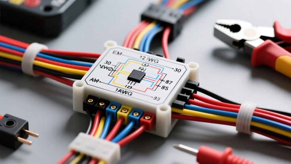
The fuse box is essentially a hub for relays. Relays allow a low-current switch (like a dashboard button or a computer transistor) to control a high-current load (like a starter motor or cooling fan). Most automotive diagrams adhere to the DIN 72552 standard for relay terminal numbering. Understanding these five numbers is mandatory for reading fuse box schematics:
- Pin 30: Constant high-current power input from the battery (usually protected by a high-amp fuse).
- Pin 87: High-current output to the load (e.g., the fuel pump or headlight).
- Pin 87a: Secondary output for 'normally closed' relays (receives power when the relay is OFF).
- Pin 85: Ground side of the low-current electromagnetic coil.
- Pin 86: Switched power side of the low-current electromagnetic coil.
Expert Note: While 85 and 86 are technically interchangeable on a standard mechanical relay coil, many modern OEMs install a suppression diode across the coil to protect sensitive ECU drivers from voltage spikes. If a diagram shows a diode symbol inside the relay coil, polarity matters. Reversing 85 and 86 on a diode-protected relay will blow the control fuse instantly.
Step-by-Step Circuit Tracing: The Fuel Pump Example
Let us trace a classic GM-style fuel pump circuit using a wiring diagram for fuse box diagnostics. The customer reports a no-start condition, and the fuel pump does not prime when the key is turned to the 'ON' position.
- Locate the Power Feed: Find the 'F/PMP' fuse (typically 20A) in the underhood fuse block. The diagram shows B+ (Battery Positive) entering the fuse, and a Red (RD) 12 AWG wire exiting toward the Fuel Pump Relay Pin 30.
- Verify the Load Side: From Relay Pin 87, a Gray (GY) 14 AWG wire exits the fuse box. The diagram indicates this wire travels through the main body harness, passes through a bulkhead connector (C100), and eventually hits a splice (S102) before dropping into the fuel tank to the pump motor.
- Trace the Control Side: The diagram shows Relay Pin 86 receiving Ignition 1 (IGN1) voltage via a Pink (PK) 18 AWG wire. Relay Pin 85 is controlled by the Powertrain Control Module (PCM). The PCM provides a switched ground path via a Dark Green/White (DK GRN/WH) 20 AWG wire connected to PCM Connector 2, Pin 22.
- Identify the Ground: The fuel pump motor itself requires a ground to complete the circuit. The diagram shows a Black (BK) 14 AWG wire leaving the pump and terminating at Ground Point G402, located on the rear chassis crossmember.
By reading the diagram, you now know that if the Gray wire at the fuse box has 12 volts during engine cranking, but the pump is silent, the fault is either an open circuit in the Gray wire, a failed splice at S102, or a corroded ground at G402. You have isolated the fault without blindly replacing the pump.
Splices, Connectors, and Ground Points
Beginners often confuse splices with connectors. In a wiring diagram, a solid black dot where two wires intersect is a Splice (S). This is a physical, soldered or ultrasonically welded junction buried deep inside the wire harness. You cannot simply 'unplug' a splice. Conversely, a connector is denoted by a dashed line or a specific cavity chart (e.g., Aptiv/Delphi Metri-Pack or GT series connectors) and is labeled with a 'C' (e.g., C205). Connectors can be unplugged for testing.
Ground points are labeled with a 'G' (e.g., G104, G200). A massive percentage of automotive electrical faults are caused by poor grounds. If your diagram shows three different modules sharing Ground G104, and all three modules are throwing communication codes, do not replace the modules. Clean and retighten the G104 bolt on the chassis first.
Modern Evolution: Solid-State Smart Fuses
If you are looking at a wiring diagram for a late-model vehicle (2015 and newer), you may notice a distinct lack of traditional mechanical relays in the interior fuse box. Modern Body Control Modules utilize High-Side and Low-Side solid-state drivers (MOSFETs) to control lighting, wipers, and window motors. These are often referred to as 'Smart Fuses' or 'e-Fuses'.
On a schematic, instead of a relay symbol, you will see a module box with a pin labeled 'LR TURN LAMP DRIVER'. These circuits do not have a physical filament fuse; the BCM monitors the current draw electronically. If a short to ground occurs, the BCM instantly shuts off the MOSFET and logs a Diagnostic Trouble Code (DTC) such as U0073 or a specific B-code for 'Short to Ground - Circuit Shut Down'. To reset a smart fuse, you must clear the DTC with a bi-directional scan tool; physically pulling a fuse will not reset the logic board.
Common Diagnostic Pitfalls When Using Diagrams
| Beginner Pitfall | What the Diagram Actually Shows | Correct Diagnostic Action |
|---|---|---|
| Assuming all grounds are on the engine block. | Ground G102 is located on the left A-pillar kick panel. | Remove interior trim to locate, clean, and torque the G102 bolt to 9 Nm. |
| Probing a wire and causing a short. | The wire is a 20 AWG TXL data bus (CAN-H). | Use a T-pin or back-probe the connector cavity; never pierce data wires. |
| Replacing a relay that clicks but doesn't work. | Pin 87 shows a 50A Maxi-fuse upstream that is blown. | Test for B+ at Pin 30 before condemning the relay or the load component. |
| Misreading a crossed wire as a connection. | Wires cross without a solid black dot (no splice). | Understand the wires are independent and share no electrical continuity. |
Essential Tools for Diagram Verification
A wiring diagram for fuse box analysis is only as good as the tools you use to verify it. Ditch the incandescent test light; it draws too much current and can fry sensitive PCM drivers. Instead, invest in a high-impedance Digital Multimeter (DMM) with a minimum 10-megohm input impedance. For tracing high-current circuits like cooling fans or starter solenoids, a digital storage oscilloscope or an inductive current clamp will allow you to view the inrush current and voltage drop simultaneously, confirming the physical health of the circuit exactly as the OEM engineers intended.