Understanding the 3-Wire Oil Pressure Sensor Circuit
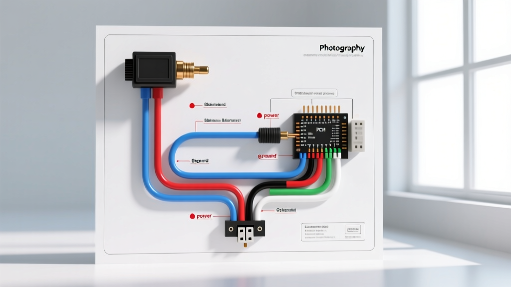
Modern powertrain control modules (PCMs) rely on precise analog feedback to monitor engine lubrication health. Unlike older single-wire mechanical switches that simply trigger a dashboard warning light at a fixed threshold (usually 5 to 7 PSI), modern 3-wire piezoelectric or strain-gauge transducers provide continuous, variable data. When consulting an OEM oil pressure sensor wiring diagram, technicians must understand that these sensors operate as part of a voltage divider network. The PCM supplies a stable 5-Volt Reference (VREF), the sensor modulates this voltage based on the physical deformation of an internal diaphragm caused by oil pressure, and a dedicated signal return wire transmits this analog voltage back to the PCM's analog-to-digital converter.
Diagnosing faults such as DTC P0520 (Oil Pressure Sensor Circuit Malfunction), P0522 (Circuit Low Voltage), or P0523 (Circuit High Voltage) requires a systematic approach. A common mistake is replacing the sensor without verifying the integrity of the 5V reference or the low-reference ground circuit. According to SAE International Technical Standards for engine management sensors, signal deviations of just 0.2V can result in drastic PCM miscalculations, potentially triggering limp-home modes or disabling variable valve timing (VVT) solenoids that rely on accurate oil pressure data.
Oil Pressure Sensor Wiring Diagram & Pinout Reference
The following table outlines the standard 3-wire configuration found on most late-model domestic and import vehicles (including GM LS/LT, Ford EcoBoost, and Chrysler HEMI platforms). The connector is typically a sealed Delphi Metri-Pack 2.8 or Weather-Pack 3-cavity assembly.
| Pin / Cavity | Circuit Function | Typical Wire Color (GM/Ford) | Wire Gauge (AWG) | Voltage Specification |
|---|---|---|---|---|
| Pin A | 5V Reference (VREF) | Gray / Red-White | 20 AWG (XLPE) | 4.8V - 5.2V (KOEO) |
| Pin B | Signal Return | Tan/White / Green-Brown | 20 AWG (XLPE) | 0.5V (0 PSI) to 4.5V (100+ PSI) |
| Pin C | Low Reference (Ground) | Black / Black-Orange | 20 AWG (XLPE) | < 0.05V (Voltage Drop) |
Note: Wire colors vary by manufacturer and model year. Always verify against the specific vehicle service manual or OEM schematic before piercing wires or back-probing connectors.
Step-by-Step Diagnostic Troubleshooting Flow
Use the following decision-tree methodology to isolate electrical faults from mechanical engine failures. This flow assumes you have already verified the engine oil level and confirmed mechanical oil pressure using a calibrated mechanical gauge.
Step 1: Live Data & Symptom Verification
Connect a bi-directional scan tool and monitor the Oil Pressure PID with the Key On, Engine Off (KOEO). A healthy 3-wire sensor should read between 0 and 2 PSI (approx. 0.4V to 0.6V). Start the engine. The PID should immediately ramp up to 30-60 PSI (1.5V to 3.0V) depending on oil temperature and RPM. If the PID reads exactly 0 PSI or 255 PSI, you have a hard electrical fault (short to ground or short to VREF/open circuit). If the reading fluctuates erratically by more than 10 PSI at a steady RPM, suspect electromagnetic interference (EMI) or a failing internal sensor potentiometer.
Step 2: Visual & Physical Harness Inspection
Oil pressure sensors are typically located low on the engine block or near the oil filter housing, exposing the wiring harness to extreme heat, road debris, and oil saturation. Inspect the harness for capillary wicking—a phenomenon where oil breaches a degraded connector seal and travels up the wire strands under the insulation, eventually reaching the PCM connector. Check for chafing against the exhaust manifold or engine lifting brackets. If the harness is oil-logged at the PCM side, the entire engine harness must be replaced or meticulously cleaned with electrical contact solvent, as oil will degrade the PVC and XLPE insulation over time.
Step 3: Reference Voltage (VREF) Verification
Disconnect the sensor connector. Turn the ignition to the ON position (KOEO). Using a digital multimeter (DMM) set to DC Volts, back-probe Pin A (VREF) against a known good engine ground. You must read between 4.8V and 5.2V.
- If VREF is 0V: There is an open circuit between the PCM and the sensor, or the PCM's internal 5V regulator has shorted. Check for shared VREF circuits (e.g., MAP sensor, TP sensor) that may be pulling the 5V bus down.
- If VREF is below 4.8V: Perform a voltage drop test on the VREF wire from the PCM breakout box to the sensor connector to identify high resistance or corrosion.
Step 4: Signal Return Circuit Testing
With the sensor still disconnected and KOEO, measure the voltage at Pin B (Signal Return). It should read approximately 4.8V to 5.0V (pull-up voltage from the PCM). Now, use a fused jumper wire to briefly bridge Pin B (Signal) to Pin C (Ground). Monitor the scan tool PID. The oil pressure reading should instantly drop to 0 PSI, and the voltage on the DMM should drop to near 0V. If the scan tool does not react, the signal wire is open between the sensor and the PCM.
Step 5: Sensor Ground Integrity Check
A poor sensor ground will artificially inflate the signal voltage, causing the PCM to read higher oil pressure than actually exists, potentially masking a dangerous mechanical failure. Set your DMM to DC Volts. Connect the red lead to Pin C (Low Reference) at the sensor harness and the black lead to the negative battery terminal. With the engine running and electrical loads (headlights, HVAC blower) turned ON, the voltage drop must be less than 0.05V. A reading higher than 0.10V indicates a corroded PCM ground splice or a loose engine block ground strap.
Advanced Diagnostics: Oscilloscope & EMI Analysis
When dealing with intermittent DTC P0521 (Range/Performance) codes that only set under heavy acceleration or specific RPM ranges, a DMM is insufficient due to its slow sample rate. Connect a lab oscilloscope to the Signal Return wire. A healthy sensor will show a clean, flat DC voltage line that transitions smoothly with RPM changes.
According to diagnostic procedures outlined by Motor Information Systems, if the oscilloscope trace displays high-frequency 'hash' or voltage spikes synced with engine RPM, the signal wire is likely suffering from inductive cross-talk. This is highly common on engines where the oil pressure sensor harness is routed too closely to ignition coil primary circuits or alternator output cables. Rerouting the harness or wrapping the sensor circuit in a grounded copper-foil shielding tape will resolve the EMI interference.
Repair Best Practices & Installation Specifications
When replacing the sensor or repairing the pigtail, adhere to the following professional standards to prevent repeat failures:
- Wire Splicing: Never use twist-on crimp connectors or electrical tape in the engine bay. Use heat-shrink solder sleeves with a dual-wall adhesive lining to create a waterproof, vibration-proof seal.
- Connector Terminals: If replacing a Metri-Pack terminal, use the correct crimp tool (e.g., Delphi HT-200) to ensure the wire crimp and insulation crimp are properly formed. Apply a small dab of dielectric grease to the connector seal ring, but never on the terminal pins themselves, as it can increase contact resistance.
- Thread Sealant: Most modern oil pressure sensors utilize tapered NPT or straight M14x1.5 threads with an O-ring seal. If your sensor uses tapered threads, do not use standard PTFE (Teflon) tape. Tape shreds can enter the oil galleries and block VVT solenoid screens. Instead, use a liquid anaerobic thread sealant rated for petroleum exposure, and torque the sensor to the manufacturer's specification (typically 15 Nm / 11 lb-ft for M14 sensors) to prevent cracking the sensor housing or the aluminum engine block.