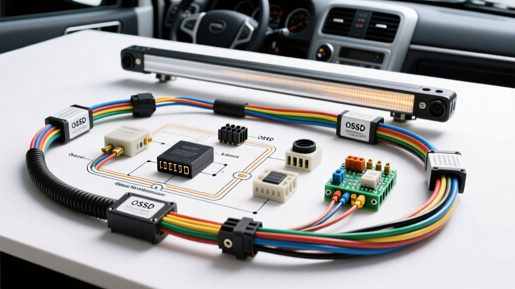
Introduction to Mobile Machinery Light Curtains
In the realm of automated heavy machinery, autonomous mining haul trucks, and port-side Automated Guided Vehicles (AGVs), pedestrian safety is paramount. Unlike stationary factory presses, mobile heavy vehicles operate in dynamic, high-vibration environments where safety systems are subjected to extreme mechanical and electrical stress. At the core of these vehicle safety systems is the safety light curtain—an optoelectronic protective device that creates an invisible infrared barrier around the vehicle's hazard zones. However, integrating these sensors into a mobile vehicle's 24V DC electrical architecture requires strict adherence to safety protocols. A flawed light curtain sensor wiring diagram can lead to catastrophic failures, bypassing the safety logic and resulting in severe injury or fatal collisions.
This technical guide explores the precise wiring schematics for heavy-vehicle light curtain receivers, details the Output Signal Switching Device (OSSD) routing, and highlights the most common, life-threatening wiring mistakes made by mobile machinery technicians.
Understanding the Light Curtain Sensor Wiring Diagram
Modern vehicular safety light curtains, such as those manufactured by SICK or Keyence, operate on a dual-channel redundancy principle. The system consists of an Emitter (which sends the infrared pulses) and a Receiver (which detects them and interfaces with the vehicle's safety PLC or safety relay). The most critical component of the light curtain sensor wiring diagram is the Receiver's OSSD outputs. These outputs do not simply "open" or "close" a circuit; they continuously pulse a 24V DC safety signal. If the receiver's internal microprocessors detect a fault, cross-talk, or a broken infrared beam, both OSSD channels immediately drop to 0V, triggering the vehicle's dynamic braking system.
For heavy-duty AGVs and autonomous straddle carriers, the receiver is typically terminated with an IP69K-rated M12 8-pin circular connector to withstand high-pressure washdowns and severe vibration.
M12 8-Pin Receiver Pinout Specification
Below is the standard pinout configuration for a Category 4, PLe rated safety light curtain receiver integrated into a mobile machine's safety loop.
| Pin | Wire Color | Function | AWG / Spec | Description |
|---|---|---|---|---|
| 1 | Brown | +24V DC (Power) | 18 AWG | Main power supply. Must be fused at 2A max. |
| 2 | White | OSSD 1 (Output A) | 20 AWG Shielded | Channel 1 Safety Output to Safety Relay. |
| 3 | Blue | 0V DC (Ground) | 18 AWG | Logic and Power Ground reference. |
| 4 | Black | OSSD 2 (Output B) | 20 AWG Shielded | Channel 2 Safety Output to Safety Relay. |
| 5 | Grey | EDM (Feedback) | 22 AWG Shielded | External Device Monitoring input from contactors. |
| 6 | Pink | Mute / Test | 22 AWG | Used for automated pallet muting or self-test triggers. |
| 7 | Violet | Reset | 22 AWG | Manual or automatic reset input post-fault. |
| 8 | Orange/Yellow | Shield / Drain | Braid | Cable shield termination (grounded at PLC end only). |
5 Critical Wiring Mistakes That Compromise Safety
When technicians transition from standard automotive 12V wiring to industrial 24V safety systems, they often apply standard automotive practices to safety-critical circuits. This is a severe violation of ISO 13849-1 standards for mobile machinery. Below are the most dangerous mistakes found in vehicular light curtain installations.
Mistake 1: Defeating External Device Monitoring (EDM)
The Error: To save time or bypass a faulty brake contactor, a technician wires a jumper between the +24V supply and the EDM input (Pin 5) on the receiver.
The Danger: EDM is a closed-loop feedback system. It verifies that the vehicle's main safety contactors or solid-state relays have actually opened when the OSSD signals drop to 0V. If a contactor welds shut due to high inrush currents from the AGV's drive motors, the EDM circuit detects the discrepancy and locks the light curtain in a permanent safe state. Bypassing the EDM means the vehicle will continue to drive forward even if the safety relay fails, rendering the light curtain completely useless.
Mistake 2: Inductive Coupling on OSSD Lines
The Error: Routing the White (OSSD 1) and Black (OSSD 2) wires in the same wiring loom as the heavy-gauge (2/0 AWG) motor drive cables powering the vehicle's traction inverters.
The Danger: The traction motors on a 40-ton autonomous mining truck draw hundreds of amps, creating massive electromagnetic interference (EMI). Because OSSD signals rely on high-frequency pulsing to detect short circuits and cross-wiring, inductive coupling from the motor cables can induce "ghost voltages" on the OSSD lines. The safety relay interprets these ghost voltages as a valid 24V signal, failing to stop the vehicle when a pedestrian breaks the infrared beam. Always route OSSD lines in a separate, grounded metallic conduit or use heavily shielded twisted-pair cables (e.g., Belden 8723).
Mistake 3: Undersized Power Conductors Causing Voltage Drop
The Error: Using 22 AWG wire for the main power (Pin 1) and ground (Pin 3) on a harness that runs 15 meters from the vehicle's main power distribution module to the front bumper sensor array.
The Danger: Safety light curtains require a stable 24V DC supply (typically ±15%). A 15-meter run of 22 AWG wire will experience significant voltage drop, especially during engine cranking or when high-draw accessories (like beacon strobes) activate. If the voltage at the receiver drops below 19.2V, the internal safety microprocessors will trigger a lockout, causing the AGV to perform an emergency stop in the middle of a busy traffic lane. Always use a minimum of 18 AWG for power circuits on mobile harnesses exceeding 5 meters.
Mistake 4: Grounding the Shield at Both Ends
The Error: Terminating the cable shield (Pin 8) to the chassis ground at both the sensor end and the safety PLC end.
The Danger: Heavy vehicles suffer from severe ground potential differences between the front chassis and the rear control cabinet due to high-current return paths. Grounding the shield at both ends creates a ground loop, turning the cable shield into an antenna that injects high-frequency alternator whine and inverter noise directly into the OSSD signal wires. The shield must only be grounded at the controller (PLC) end, leaving the sensor end floating or connected via a high-frequency capacitor.
Mistake 5: Ignoring IP69K Connector Torque Specs
The Error: Hand-tightening the M12 connector on the receiver without using a calibrated torque wrench.
The Danger: Mobile machinery operates in environments with heavy rain, mud, and high-pressure washdowns. The IP69K rating of the sensor is only valid if the M12 connector is tightened to the manufacturer's exact specification (typically 0.4 Nm to 0.6 Nm). Under-tightening allows water ingress, leading to internal corrosion and OSSD short-to-ground faults.
OSSD Troubleshooting Decision Tree
When an AGV or heavy vehicle is immobilized due to a light curtain fault, technicians must follow a systematic diagnostic approach. Do not attempt to reset the system without identifying the root cause.
- Symptom: OSSD 1 and OSSD 2 flashing red simultaneously.
- Cause: Internal receiver microprocessor mismatch or optical element occlusion.
- Fix: Clean the optical lenses with isopropyl alcohol. Check alignment using the laser tool. If clear, replace the receiver unit.
- Symptom: OSSD 1 solid red, OSSD 2 flashing.
- Cause: Cross-wiring short between OSSD 1 and OSSD 2, or a short to +24V.
- Fix: Disconnect the M12 connector. Use a multimeter to check continuity between Pin 2 and Pin 4. Inspect the harness for crush damage near the vehicle's articulation joints.
- Symptom: System locks out immediately upon EDM reset.
- Cause: EDM feedback timing violation (contactors are opening too slowly) or EDM wired to a solid-state relay without a bleed resistor.
- Fix: Measure contactor dropout time (must be < 20ms). Install a bleeder resistor across the SSR inputs to prevent leakage current from tricking the EDM circuit.
Industry Standards and Compliance
Integrating a light curtain sensor wiring diagram into a vehicle is not a casual modification. It must comply with stringent mobile machinery safety standards. According to SICK Safety Guidelines, any optoelectronic protective device used on autonomous or semi-autonomous vehicles must meet IEC 61496-1 Type 4 requirements. Furthermore, the integration of the safety relay with the vehicle's broader control network must adhere to SAE J1939 protocols, ensuring that a safety trip generates the correct CAN bus priority messages to halt the engine and apply the pneumatic parking brakes instantly.
Always consult the specific OEM wiring schematics and utilize certified safety relays (such as Pilz PNOZ or Allen-Bradley Guardmaster) designed specifically for the high-vibration, high-EMI environment of heavy-duty automotive applications.