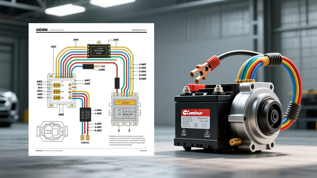
Introduction to Cummins Cranking Systems and Wiring Architecture
When diagnosing a no-crank condition or planning a high-torque starter upgrade on a Dodge Ram equipped with a 5.9L or 6.7L Cummins turbo diesel, understanding the underlying electrical architecture is critical. The Cummins starter wiring diagram is not a simple direct-feed circuit; it is a heavily integrated system managed by the Powertrain Control Module (PCM) or Engine Control Module (ECM), relying on heavy-gauge battery cables and precise low-amperage signal wires. Selecting the right starter motor—whether sticking with an OEM Denso direct-drive unit or upgrading to an aftermarket gear-reduction model—fundamentally alters the current draw, voltage drop parameters, and wiring requirements of your cranking circuit.
This guide compares the electrical demands of OEM versus aftermarket starter options, provides detailed wiring schematics, solenoid pinouts, and battery cable AWG sizing charts, and outlines real-world troubleshooting steps for common Cummins cranking failures. According to SAE J541 standards for heavy-duty starter motor performance, cranking a high-compression diesel engine requires massive instantaneous amperage, making wiring integrity just as important as the starter motor itself.
Product Selection Guide: OEM Direct-Drive vs. Gear-Reduction
Before modifying or repairing your wiring harness, you must select the appropriate starter motor. The electrical footprint of the starter dictates the necessary wire gauge and relay specifications.
Option 1: OEM Denso Direct-Drive (1.4kW - 1.7kW)
Factory-equipped on most 1994-2007 5.9L Cummins engines, the OEM Denso direct-drive starter relies on a traditional armature and field coil design. While reliable when new, these units draw massive amperage (often exceeding 500A under load) to generate sufficient torque. This high current draw exacerbates voltage drop across aging battery cables and factory grounding points, frequently leading to slow cranking speeds and premature solenoid contact failure.
Option 2: Aftermarket High-Torque Gear-Reduction (2.2kW - 3.0kW)
Upgrading to a gear-reduction starter (such as the Remy 9000 series or Powermaster XS Torque) utilizes a planetary gear set to multiply torque at the flywheel. Because the electric motor spins at a higher RPM with less mechanical load, these units typically draw 30% to 40% less amperage (250A - 350A) while delivering significantly higher cranking torque. From a wiring perspective, this is a massive advantage: lower amperage draw means reduced voltage drop, less heat generation in the positive battery cables, and extended lifespan for the starter relay contacts.
Cummins Starter Wiring Diagram & Circuit Configurations
The wiring diagram for a Cummins starter varies significantly between the Generation 2 (1994-2002) and Generation 3/4 (2003-2018) platforms. The primary difference lies in how the starter solenoid receives its 'Start' signal.
Generation 2 (1994-2002): Ignition Switch Fed
In older 12-valve and early 24-valve applications, the ignition switch directly powers the starter relay coil. When the key is turned to 'START', 12V is sent to Pin 86 of the starter relay. The relay coil is grounded at Pin 85. When energized, the relay connects Pin 30 (constant battery power) to Pin 87, sending 12V down the starter signal wire to the solenoid's 'S' terminal.
Generation 3 & 4 (2003-2018): ECM/PCM Controlled Ground
Modern 5.9L and 6.7L Cummins engines utilize an ECM-controlled starter relay circuit for safety and emissions compliance (preventing cranking during DPF regeneration or while in gear). In this Cummins starter wiring diagram, the ignition switch sends a 12V logic signal to the ECM. The ECM then provides the ground path for the starter relay coil (Pin 85). If the ECM does not see the correct security codes, transmission range sensor inputs, or brake pedal position, it will not ground the relay, resulting in a no-crank condition despite having perfect wiring to the starter itself.
Solenoid Terminal Pinout & Wire Color Codes
Whether using an OEM Denso or an aftermarket gear-reduction unit, the solenoid terminal configurations remain largely standardized. Below is the reference table for terminal identification, wire routing, and Dodge Ram factory color codes.
| Terminal ID | Stud Size | Function | Wire Color (Typical Gen 3) | Connection Destination |
|---|---|---|---|---|
| B+ (Battery) | M10 (10mm) | Main Cranking Power | Red (2/0 AWG or 4/0 AWG) | Positive Battery Terminal via Fusible Link |
| S (Start) | M4 or M5 | Solenoid Pull-in Signal | Dark Blue / Yellow Tracer | Starter Relay Pin 87 |
| I (Ignition) | M4 or M5 | Ballast Bypass (Unused on Diesel) | N/A (Cap or Remove) | Leave Disconnected |
| M (Motor) | M10 (10mm) | Internal Motor Feed | Internal Copper Strap | Starter Yoke / Field Coils |
Note: The 'I' terminal is a carryover from gasoline applications to bypass the ignition ballast resistor during cranking. Cummins diesels do not use this. Connecting a wire to the 'I' terminal on a modern EFI diesel can cause back-feeding and ECM damage.
Battery Cable Sizing & Voltage Drop Specifications
A common mistake when replacing a Cummins starter is reusing degraded, undersized, or aluminum-clad copper (CCA) battery cables. According to Denso's technical installation guidelines, excessive voltage drop at the B+ terminal will cause the solenoid to chatter, welding the internal copper contacts together. To prevent this, cable sizing must be matched to the peak amperage draw of the selected starter.
| Starter Type | Peak Amperage Draw | Minimum Cable AWG (Up to 10ft) | Recommended Cable AWG | Max Allowable Voltage Drop |
|---|---|---|---|---|
| OEM 1.4kW Direct-Drive | 450A - 550A | 2/0 AWG | 4/0 AWG | 0.5V (Under Load) |
| OEM 1.7kW Direct-Drive | 500A - 650A | 1/0 AWG | 4/0 AWG | 0.5V (Under Load) |
| Aftermarket 2.2kW Gear-Red. | 250A - 350A | 1/0 AWG | 2/0 AWG | 0.2V (Under Load) |
| Aftermarket 3.0kW Gear-Red. | 300A - 400A | 2/0 AWG | 4/0 AWG | 0.2V (Under Load) |
Always use pure, fine-strand OFC (Oxygen-Free Copper) welding cable for custom battery runs. Avoid automotive primary wire, which lacks the strand count necessary to handle high-amperage transient spikes without generating excessive heat.
Real-World Troubleshooting & The Starter Relay Upgrade
When diagnosing a Cummins cranking issue, technicians often condemn the starter motor prematurely. A systematic approach using a digital multimeter (DMM) and a Cummins starter wiring diagram is required to isolate the fault.
Symptom: Single Loud 'Click' Followed by No Cranking
This is the hallmark of solenoid contact welding or severe voltage drop. The solenoid plunger is pulling in (the click), but the heavy copper contacts inside the solenoid cap are pitted and cannot pass the 400A+ required to spin the motor. Diagnostic Step: Perform a voltage drop test across the solenoid. Place your DMM positive lead on the B+ terminal and the negative lead on the M (Motor) terminal. Have an assistant crank the engine. If the DMM reads more than 0.5V, the internal solenoid contacts are failing, or the B+ cable has high resistance. Replace the solenoid cap or the entire starter assembly.
Symptom: Rapid Clicking or Chattering Solenoid
Chattering occurs when the solenoid pulls in, drawing massive current, which causes the system voltage to drop below the solenoid's holding threshold. The solenoid releases, voltage recovers, and it pulls in again. Diagnostic Step: This is almost always caused by undersized battery cables, corroded ground straps, or a failing starter relay. The factory Dodge Ram starter relay contacts are rated for roughly 30A-40A. Over time, arcing pits these contacts, increasing resistance and starving the starter solenoid of the necessary 12V signal.
The 'Big 3' Starter Relay Upgrade
For trucks running aftermarket gear-reduction starters or those operating in extreme cold, upgrading the starter signal circuit is highly recommended. By installing an external, heavy-duty 80A continuous-duty relay (such as a White-Rodgers or Bosch heavy-duty unit) near the starter, you bypass the factory PDC/TIPM relay entirely.
- Run a dedicated 10 AWG fused wire directly from the battery positive to Pin 30 of the new heavy-duty relay.
- Run an 8 AWG wire from Pin 87 of the new relay directly to the starter solenoid 'S' terminal.
- Use the factory starter signal wire (Dark Blue/Yellow) to trigger Pin 86 of the new relay.
- Ground Pin 85 to the engine block using a dedicated 10 AWG ground wire.