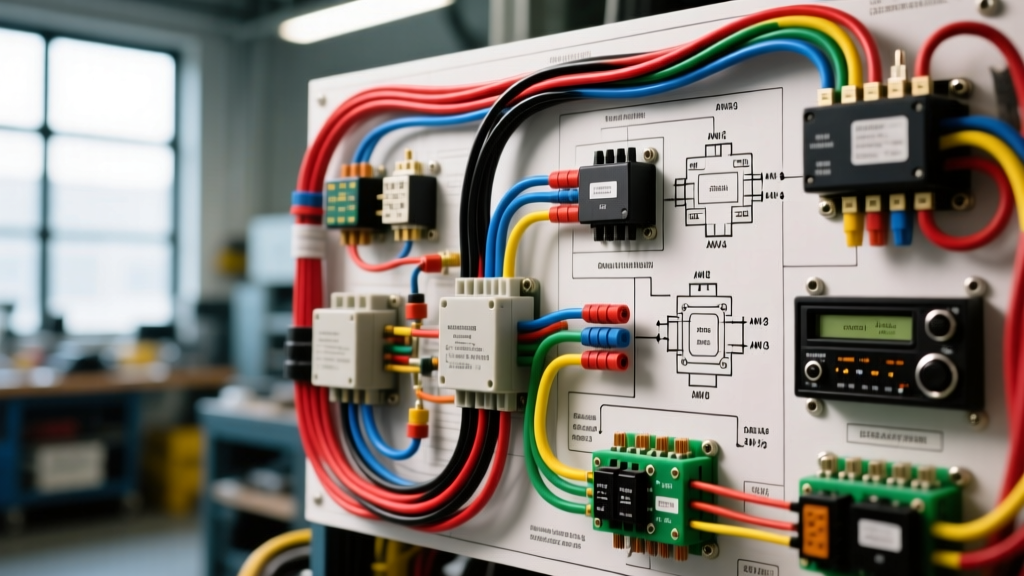
Understanding the Dual Radio Modification Challenge
Executing an upgrade and modification project that involves installing a secondary head unit requires far more than simply splicing into the factory harness. Whether you are building an overland expedition vehicle with a rear-cabin passenger control unit, an RV with zone-specific audio, or an off-road rig integrating HAM radio communications alongside a digital media receiver, finding the correct wiring diagram for dual radio configurations is critical. The most common failure point in these custom builds is the mishandling of the Accessory (ACC) power wire and the shared ground planes, which leads to CAN-bus backfeeding, parasitic battery drains, and severe alternator whine.
When you parallel the ACC (typically Red) and Constant 12V (typically Yellow) wires of two head units directly together, turning on the secondary radio can backfeed voltage into the vehicle's ignition switch circuit or wake up the primary radio's CAN-bus network. This prevents the vehicle's ECU from entering sleep mode, draining the battery overnight. To prevent this, a proper dual radio wiring schematic utilizes relay isolation and dedicated power distribution blocks. This guide details the exact wire gauges, relay pinouts, and signal isolation techniques required for a professional-grade dual head unit installation.
Power and Ground Distribution Specifications
Adhering to SAE J1128 standards for low-tension primary automotive cable ensures your wiring can handle the thermal and electrical loads of dual amplifiers and head units without excessive voltage drop. The secondary radio must have its own dedicated power and ground runs back to the battery or a centralized distribution block, rather than daisy-chaining off the primary radio's harness.
| Circuit Function | Wire Color (Standard) | AWG Size (Up to 15ft Run) | Protection / Fuse | Termination Point |
|---|---|---|---|---|
| Primary Radio Constant 12V | Yellow | 14 AWG | 15A Inline Fuse | Battery Positive or OEM Fuse Box |
| Primary Radio ACC (Switched) | Red | 16 AWG | Tapped via Add-A-Circuit | Ignition Switch / CAN-bus Interface |
| Secondary Radio Constant 12V | Yellow | 12 AWG | 20A Inline Fuse | Secondary Distribution Block |
| Secondary Radio ACC (Isolated) | Red (Relay Output) | 16 AWG | 10A Inline Fuse | Relay Pin 87 |
| Shared System Ground | Black | 10 AWG | N/A | Bare Metal Chassis (Sanded) |
The Wiring Diagram for Dual Radio Relay Isolation
To safely switch the secondary radio on and off without backfeeding the primary ignition circuit, you must use a standard Bosch-style 5-pin automotive relay. This relay acts as a one-way electrical gate. The primary radio's ACC wire (or a dedicated 12V trigger from a PAC interface module) will serve as the low-amperage switch signal, while the secondary radio draws its high-amperage ACC power directly from the battery through the relay's internal contactor.
Standard Bosch 5-Pin Relay Pinout for ACC Isolation
- Pin 85 (Coil Ground): Connect to a clean, bare-metal chassis ground using 16 AWG wire and a ring terminal. Apply dielectric grease to prevent corrosion.
- Pin 86 (Coil Trigger): Connect to the Primary Radio's ACC (Red) output wire, or the remote turn-on lead of your primary zone's amplifier. This wire only carries a few milliamps and simply activates the electromagnet inside the relay.
- Pin 30 (Common Input): Connect to your Secondary Distribution Block's fused 12V Constant source (12 AWG). This is the raw power waiting to be sent to the second radio.
- Pin 87 (Normally Open Output): Connect to the Secondary Radio's ACC (Red) wire. When Pin 86 receives 12V from the primary radio, the internal switch closes, sending power from Pin 30 to Pin 87, waking up the secondary radio.
- Pin 87a (Normally Closed): Tape off and insulate this pin. It is not used in this specific isolation diagram.
By utilizing this relay logic, the secondary radio remains completely isolated from the vehicle's sensitive CAN-bus and ignition circuits. Even if the secondary radio develops an internal short to power, the inline 10A fuse on Pin 30 will blow without risking the primary vehicle harness. For harsh environments like marine or off-road builds, house this relay in a sealed Bosch weatherproof relay box with Molex MX150 sealed connectors to prevent moisture ingress and terminal oxidation.
Signal Routing and Ground Loop Prevention
The most frustrating issue in dual radio modifications is alternator whine—a high-pitched squeal that rises and falls with engine RPM. This occurs when the primary and secondary radios (or their respective amplifiers) are grounded at different points on the chassis that possess slightly different electrical potentials. According to automotive electrical principles, voltage will flow through the RCA cable shields to equalize this potential difference, introducing electromagnetic interference (EMI) directly into the audio signal path.
Rules for Dual Zone Audio Signal Routing
- Star Grounding Topology: Both the primary and secondary audio grounds must meet at a single, massive grounding point (a 'star ground') bolted directly to the chassis. Never ground the secondary radio to a seatbelt bolt or a thin sheet metal bracket in the rear of the vehicle.
- Digital Line Drivers: If you are running RCA cables from the front dash to a rear-cabin secondary amplifier, the long cable run acts as an antenna for EMI. Use a digital line driver (such as those from AudioControl or PAC) to boost the signal voltage from 2V to 8V+ at the source, then attenuate it at the amplifier. This drastically improves the signal-to-noise ratio.
- Speaker Zone Switching: Never wire the speaker outputs of two different head units in parallel to the same set of speakers. This creates an impedance mismatch (dropping a 4-ohm load to 2 ohms or lower) which will instantly trigger the thermal protection circuit in modern Class-D amplifiers or fry the internal IC of the head unit. Use a heavy-duty relay-based speaker selector switch or dedicated multi-zone amplifiers with independent input stages.
Troubleshooting Common Dual Head Unit Failures
Even with a meticulous wiring diagram for dual radio setups, real-world variables can introduce faults. Use a digital multimeter (DMM) to diagnose these common modification failures.
Symptom: Parasitic Battery Draw (Secondary Radio Stays On)
The Cause: If you bypassed the relay and spliced the ACC wires together, the secondary radio's internal capacitors or CAN-bus transceiver may be backfeeding voltage into the primary ignition circuit. Alternatively, the relay installed between Pin 30 and Pin 87 may have welded its internal contacts shut due to an inrush current spike when the secondary radio was first powered on.
The Fix: Disconnect the secondary radio's ACC wire at the relay. Set your DMM to measure DC Voltage. Probe the disconnected wire. If you read 12V with the vehicle completely off and the primary radio removed, you have a backfeed issue. Install a diode (rated for at least 5A, such as a 6A10) in-line on the trigger wire (Pin 86) to enforce one-way current flow, or replace the welded relay.
Symptom: Severe Voltage Drop at Secondary Radio
The Cause: The secondary radio reboots randomly when the subwoofer amplifier hits heavy bass transients. This is caused by using undersized wire (e.g., 18 AWG) for the Constant 12V (Yellow) memory wire, or a poor crimp connection at the distribution block.
The Fix: Perform a voltage drop test. Set your DMM to DC Volts. Place the red probe on the battery positive terminal and the black probe on the secondary radio's Yellow wire pin (while under heavy audio load). A reading higher than 0.2V indicates excessive resistance. Upgrade the Constant 12V run to 12 AWG OFC (Oxygen-Free Copper) wire and re-crimp the terminals using a proper ratcheting crimper and adhesive-lined heat shrink tubing to ensure a gas-tight seal.
Final Integration and Safety Checks
Before securing the secondary head unit into its custom dash or overhead console mount, verify all connections. Ensure that all T-taps and scotch-locks have been removed and replaced with proper solder-seal butt connectors or OEM-style terminal crimps. Reference the specific PAC Audio interface manuals if you are utilizing a CAN-bus decoder to retain steering wheel controls for both zones. Proper execution of this dual radio wiring diagram guarantees a reliable, noise-free audio environment that withstands the rigorous electrical demands of modern vehicle platforms.