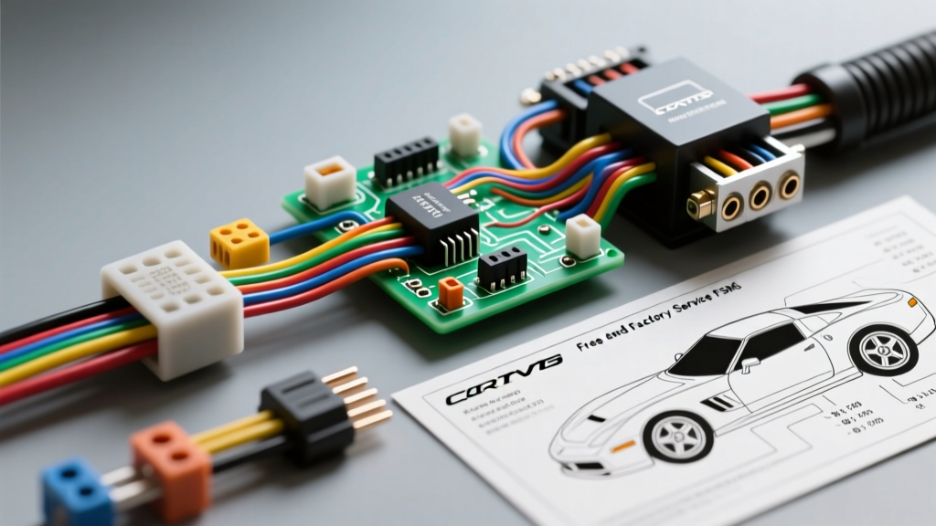
The Reality of Searching for Corvette Wiring Diagrams Free
When enthusiasts and independent mechanics search for Corvette wiring diagrams free, they are often met with a frustrating reality: generic schematics that lack the critical detail required to diagnose modern automotive electrical faults. While free resources can provide basic routing for a 1969 C3 tail light circuit, they frequently fail to map the complex multiplexed networks, splice pack locations, and terminating resistor values found in C5, C6, C7, and C8 generations. As an automotive electrical specialist, I evaluate diagram sources not just by their cost, but by their technical depth, accuracy, and usability in a real-world shop environment.
Selecting the right wiring resource is a product comparison problem. You are weighing the accessibility of community-driven archives against the precision of Factory Service Manuals (FSM). A missing ground point identifier (like G102) or an omitted Class 2 serial data line can turn a two-hour diagnostic job into a multi-day nightmare. This guide compares the leading platforms for Corvette schematics, breaks down the generational shifts in GM wiring architecture, and provides the technical specifications you need to verify if a diagram is actually worth your time.
Resource Comparison: Free Archives vs. Factory Service Manuals
To effectively troubleshoot a Corvette, you must understand the limitations of your reference material. Below is a comparative analysis of the most common sources for Corvette wiring diagrams, evaluated on technical depth, network mapping, and physical location data.
| Resource Type | Examples | Technical Depth | Best Use Case |
|---|---|---|---|
| Free Community Archives | DigitalCorvettes, CorvetteForum | Low-Medium. Often lacks splice packs (SP) and ground (G) locations. | C1-C3 restorations, basic lighting, and starter circuits. |
| Free Auto Parts Portals | AutoZone, FreeAutoMechanic | Low. Generic GM diagrams, rarely Corvette-specific module pinouts. | Quick reference for standard sensor wire colors (e.g., MAF, O2). |
| OEM Factory Service Manuals | Helm Incorporated (Official GM Publisher) | Exceptional. Includes GMLAN networks, SP/G identifiers, and connector face views. | C4-C8 deep diagnostics, BCM/ECM programming, CAN bus faults. |
| Paid Subscriptions | ALLDATA DIY, Mitchell1 | High. OEM diagrams with interactive tracing and TSB integration. | Professional shops, complex intermittent electrical gremlins. |
While the allure of Corvette wiring diagrams free is strong, relying on them for anything beyond basic 12V power routing on a C5 or newer vehicle is a critical mistake. Modern Corvettes rely on high-speed data networks where a 2.5-volt bias is just as important as a 12V battery feed.
Generational Wiring Shifts: Why Diagram Quality Matters
The architecture of Corvette electrical systems underwent massive paradigm shifts between the C3, C4, and C5/C6 generations. A high-quality diagram must reflect these specific architectural changes.
C3 to C4 Transition: The Introduction of VATS and Early ECMs
The C4 Corvette (1984-1996) introduced the Vehicle Anti-Theft System (VATS) and early Electronic Control Modules. Free diagrams often show the starter circuit but omit the VATS interlock. The VATS module reads the resistance of a pellet embedded in the ignition key. There are 15 possible resistor values, ranging from 402 ohms to 11800 ohms. If the module does not see the correct resistance on the Purple/White (PK/WH) wire at Pin B2, it will disable the starter enable relay and the fuel injectors via the Yellow (YE) wire. A proper FSM diagram will detail the exact pinout of the 10-way VATS module connector, whereas free PDFs usually leave this blank.
C5 to C8 Era: Multiplexing and GMLAN Networks
Starting with the C5 (1997+) and maturing in the C6 (2005-2013), GM implemented complex multiplexing. The C6 relies heavily on the Global Manufacturing LAN (GMLAN). According to SAE International network standards, diagnosing a GMLAN fault requires a diagram that explicitly shows the 120-ohm terminating resistors located inside the ECM and BCM.
On a C6 Corvette, the High-Speed (HS) GMLAN operates at 500 kbps. At the Data Link Connector (DLC), Pin 6 is Dark Green (DG) for CAN-High, and Pin 14 is Dark Blue (DL) for CAN-Low. These wires must be routed as a twisted pair to prevent electromagnetic interference (EMI). Free diagrams rarely indicate the twist rate or the exact location of the Star Connectors (splices) where the network branches to the Transmission Control Module (TCM) and Electronic Brake Control Module (EBCM). If you are chasing a U0100 (Lost Communication with ECM) code, a free diagram will not show you that the HS GMLAN splice pack is located behind the right-hand kick panel, leading to unnecessary teardowns.
Critical Connector and Wire Gauge Specifications
When repairing Corvette harnesses, matching the correct wire gauge (AWG) and connector cavity size is non-negotiable. Using 16 AWG wire in a sensor circuit designed for 20 AWG can alter the resistance enough to skew a 5-volt reference signal, triggering false diagnostic trouble codes (DTCs). Below is a reference chart for standard GM/Corvette electrical specifications.
| Circuit Type | Typical AWG | Connector Family | Terminal Style & Notes |
|---|---|---|---|
| Low-Current Sensors (MAF, IAT, TPS) | 20 AWG | Delphi Metri-Pack 150 | Female pull-to-seat. Requires specific crimp tool for 0.64mm blade. |
| High-Current Actuators (Injectors, Coils) | 16 - 18 AWG | Delphi Metri-Pack 280 | Push-to-seat. Used for circuits drawing 2A to 8A continuously. |
| Power Feeds & Grounds (ECM, BCM) | 10 - 12 AWG | Metri-Pack 630 / Weather-Pack | Heavy-duty terminals. Must be sealed with dielectric grease to prevent green rot. |
| High-Speed Data (HS GMLAN, CAN) | 22 AWG (Twisted) | Delphi GT 150 / OEM | Must maintain twisted pair geometry. Do not untwist more than 1 inch at splices. |
When utilizing resources like Digital Corvettes or other community archives, always cross-reference the wire gauge. Community members often upload hand-drawn or simplified schematics that omit the AWG size, leading to over-fused or under-gauged repair jobs that pose a severe fire risk, especially in the tightly packed engine bays of the C7 and C8 models.
How to Select the Right Diagram Source for Your Repair
To maximize your efficiency, use this decision matrix to determine whether a free diagram will suffice or if you must invest in a paid FSM or subscription:
- Symptom: Exterior Lighting or Horn Failure (C1-C4). Selection: Free Archives. These circuits are simple, fused, 12V switched or ground-switched systems. Color codes (e.g., Brown for tail lights, Dark Green for right stop) are standardized and rarely change.
- Symptom: No-Start / Security Light Illuminated (C4-C5). Selection: Paid FSM. You need the exact pinout of the Theft Deterrent Module, the resistor pellet chart, and the wiring path to the PCM's fuel enable circuit. Free diagrams rarely map the intermediate connectors (like C205 or C305) where these wires frequently break.
- Symptom: Multiple Module Communication DTCs (U-Codes) (C6-C8). Selection: Paid FSM or ALLDATA. You absolutely need the GMLAN network topology map, terminating resistor locations, and splice pack (SP) physical coordinates. Guessing on a CAN bus fault without a factory diagram will result in misdiagnosed modules.
Final Verdict on Sourcing Corvette Schematics
The search for Corvette wiring diagrams free is a rite of passage for every Corvette owner. While free resources are invaluable for historical reference, basic routing, and community support, they are fundamentally inadequate for diagnosing the serial data networks, body control module logic, and precise sensor reference voltages of modern Corvettes.
As a best practice, use free forums to identify the symptoms and common failure points (such as the notorious C5 hazard switch interrupting the turn signals), but rely on Helm Incorporated FSMs or paid professional subscriptions for the actual diagnostic tracing. Understanding GM's specific wire color abbreviations, maintaining twisted-pair integrity on data lines, and utilizing the correct Metri-Pack crimp terminals will ensure your electrical repairs are as reliable as the vehicle's original engineering.