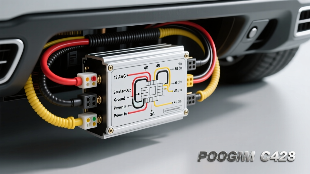
Electrical Architecture Overview
When interpreting an amplifier wiring diagram subwoofer layout, technicians must separate high-current DC power delivery from low-voltage AC audio signal paths. Improper routing or inadequate wire gauge selection is the primary cause of voltage drop, thermal throttling, and electromagnetic interference (EMI). This technical specification reference outlines the exact AWG requirements, impedance matching topologies, and OEM integration pinouts required for a stable, high-output mobile audio system.
According to the CTA-2006 Mobile Audio Amplifier Power Rating Standard, amplifier output must be measured at a strict 14.4V DC supply with a maximum 1% THD+N. Therefore, the wiring infrastructure must be engineered to maintain at least 13.8V at the amplifier's B+ terminal under peak dynamic load conditions to prevent clipping and protect the subwoofer voice coils from DC offset.
Power Delivery Circuit: AWG & Amperage Specifications
The main power circuit originates at the vehicle's positive battery terminal, passes through a primary fuse within 18 inches of the terminal, and routes to the amplifier's B+ terminal. The choice between Oxygen-Free Copper (OFC) and Copper-Clad Aluminum (CCA) drastically alters the required American Wire Gauge (AWG). CCA has approximately 30% higher resistance than OFC, necessitating a larger gauge for the same current capacity.
| Wire Gauge (AWG) | Material | Max Continuous Current | Max Subwoofer Wattage (14.4V) | Recommended Fuse Type |
|---|---|---|---|---|
| 0 AWG | OFC | 225A | 3,000W RMS | ANL (250A) |
| 0 AWG | CCA | 150A | 2,000W RMS | ANL (175A) |
| 4 AWG | OFC | 150A | 2,000W RMS | ANL/AGU (150A) |
| 4 AWG | CCA | 100A | 1,200W RMS | AGU (120A) |
| 8 AWG | OFC | 80A | 1,000W RMS | AGU/Maxi (80A) |
Note: For runs exceeding 16 feet, increase the wire gauge by one size to compensate for resistance-induced voltage drop ($V_{drop} = I \times R$).
Signal Routing & OEM Harness Integration
Modern vehicle infotainment systems utilize CAN-bus or GMLAN networks, meaning a traditional 12V Accessory (ACC) wire is often absent at the radio harness. When adapting an amplifier wiring diagram subwoofer for late-model vehicles, technicians must use a Digital Signal Processor (DSP) or an active Line Output Converter (LOC) with DC-offset detection to generate the Remote Turn-On (REM) signal.
GM Silverado/Sierra (2014-2023) Bose Audio Integration
In GM trucks equipped with the IO5/IO6 radio and Bose amplification, the radio does not output an analog 12V ACC wire. Tapping the wrong wire can backfeed the GMLAN network, causing U-codes (communication faults) in the BCM.
| Connector / Pin | Wire Color | Function | Integration Protocol |
|---|---|---|---|
| X1 / Pin 1 | Yellow/Black | Battery 12V+ | Reference Voltage (Do Not Tap for Amp Power) |
| X1 / Pin 4 | Black | Chassis Ground | LOC Ground Reference |
| X1 / Pin 13 | Light Green | GMLAN High | CAN-Bus Data (Use Interface Module for REM) |
| X2 / Pins 1-8 | Various | Amplified Speaker Outputs | Route to LOC High-Level Inputs (Summing Required) |
For the REM wire in this application, utilize an auto-turn-on module (e.g., AudioControl ACR-3) that detects the AC signal on the speaker wires, or tap the vehicle's Body Control Module (BCM) Ignition 3 circuit. Never use the power window or sunroof circuits for remote turn-on, as they retain accessory power via the RAP (Retained Accessory Power) module, which will drain the battery.
Subwoofer Impedance & Voice Coil Wiring Schematics
Matching the subwoofer's final impedance to the amplifier's stable load rating is critical. Wiring a subwoofer below the amplifier's minimum ohm threshold will trigger the thermal or short-circuit protection circuitry. The SAE J1113 Electromagnetic Compatibility Standards also dictate that high-current switching (like Class D amplifiers driving sub-1-ohm loads) requires rigorous power wire shielding to prevent radiated EMI from interfering with vehicle GPS or TPMS sensors.
Dual Voice Coil (DVC) Load Matrix
| Subwoofer Spec | Wiring Topology | Final Impedance (Ohms) | Amplifier Stability Requirement |
|---|---|---|---|
| DVC 4-Ohm | Series | 8.0 Ohms | Standard (High Efficiency, Low Heat) |
| DVC 4-Ohm | Parallel | 2.0 Ohms | 2-Ohm Stable Minimum |
| DVC 2-Ohm | Series | 4.0 Ohms | Standard (Optimal for Most Class D) |
| DVC 2-Ohm | Parallel | 1.0 Ohm | 1-Ohm Stable (Requires 0 AWG & Upgraded Alt) |
Wiring Execution: When wiring DVC subwoofers in parallel, use identical lengths of 12 AWG or 10 AWG speaker wire from the amplifier's binding posts to each voice coil terminal. Mismatched wire lengths create unequal resistance paths, causing one coil to draw more current and heat up faster, leading to mechanical failure.
Grounding Protocols & Chassis Integration
The ground circuit is not merely a return path; it is the reference point for the amplifier's internal power supply and signal inputs. A poor ground introduces a ground loop, resulting in alternator whine that scales with engine RPM.
- Location: Within 18 inches of the amplifier. Do not use factory seatbelt bolts, as they are coated with Loctite and paint, and serve as critical safety restraint anchors.
- Preparation: Remove all paint, primer, and undercoating using 80-grit sandpaper down to bare, shiny steel.
- Hardware: Use an M8 (5/16') or M10 (3/8') Grade 8 zinc-plated bolt with a star washer. The star washer bites into the bare metal to prevent oxidation and vibration loosening.
- Torque Specification: Torque the ground bolt to 15-20 Nm (11-15 lb-ft) depending on the sheet metal thickness. For unibody vehicles, use a backing nut and large fender washer on the opposite side of the chassis to distribute the clamping force.
Diagnostic Troubleshooting Matrix
When a subwoofer system fails to perform as outlined in the schematic, use this diagnostic matrix to isolate the fault based on electrical symptoms.
| Symptom | Probable Electrical Cause | Corrective Action |
|---|---|---|
| Amplifier Protect Mode (Red LED) | Shorted speaker wire or impedance below 1 Ohm. | Disconnect all speaker wires. Test amp with no load. Check DVC wiring topology. |
| Alternator Whine (RPM dependent) | Ground loop or RCA cables routed parallel to power wire. | Reroute RCA cables on opposite side of vehicle. Verify amp ground and LOC ground share same potential. |
| Subwoofer Chuffing/Clipping | Voltage drop causing square-wave clipping at the amp. | Measure B+ terminal under load. If below 12.5V, upgrade alternator or add lithium secondary battery. |
| Amp Turns Off During Heavy Bass | Remote turn-on circuit lacks current capacity. | Use a 30A Bosch-style relay triggered by the head unit REM wire to supply 12V directly from the battery to the amp REM terminal. |
For comprehensive installation methodologies and vehicle-specific harness adapters, refer to the Crutchfield Amplifier Installation Guide, which provides verified OEM wiring diagrams and integration solutions for over 10,000 vehicle applications.