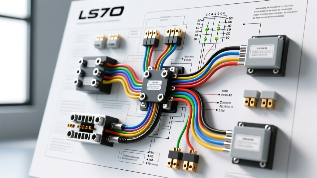
Introduction to Engine Wiring Harness Diagrams
When performing a complex powertrain swap or restoring a classic vehicle, the engine wiring harness diagram is not just a reference document; it is the definitive blueprint for your vehicle's nervous system. Misinterpreting a single circuit on the schematic can lead to catastrophic ECU failure, erratic sensor readings, or an engine that cranks but refuses to fire. For automotive technicians and advanced DIYers working with the ubiquitous GM Gen III and Gen IV LS V8 platforms, understanding how to translate a two-dimensional engine wiring harness diagram into a physical, three-dimensional installation is a critical skill. This guide breaks down the schematic legends, pinout configurations, wire gauge requirements, and physical routing protocols necessary for a flawless engine harness installation.
Decoding the Schematic: Symbols and Connector Legends
Before cutting, crimping, or routing a single wire, you must understand the visual language of the factory service manual schematics. The engine wiring harness diagram utilizes standardized symbols defined by the Society of Automotive Engineers (SAE) and specific manufacturer nomenclature. A solid dot where two lines intersect indicates a physical splice (S-node) inside the harness loom. A crossing without a dot simply means the wires pass over one another without electrical connection.
Connector cavities are typically labeled with a letter-number combination (e.g., C1-14). In GM LS applications, the Powertrain Control Module (PCM) utilizes three primary connectors: C1 (Blue), C2 (Red), and C3 (Black). The diagram will denote the connector color, the cavity number, and the specific wire color code (e.g., 'DK GN' for Dark Green). Always verify the wire color against the physical harness, as aftermarket replacement harnesses or previously modified OEM harnesses may deviate from the factory engine wiring harness diagram.
Understanding Delphi Metri-Pack and Weather-Pack Standards
The LS platform relies heavily on Delphi (now Aptiv) connector systems. The engine wiring harness diagram will reference these by their series designation. The Metri-Pack 150 series handles low-current sensor signals (like the Mass Air Flow sensor or coolant temperature), while the Metri-Pack 280 series and larger Weather-Pack connectors are used for high-current actuators like fuel injectors and ignition coils. When repairing or extending a harness based on the diagram, you must use the correct terminal crimp tool (such as the Delphi-specific ratcheting crimper) to ensure the wire barrel and insulation crimp meet OEM pull-test specifications. A standard universal crimp tool will deform the terminal tangs, leading to loose connections and intermittent voltage drops.
GM Gen III/IV PCM Pinout Reference Table
The following table highlights critical circuits derived directly from the OEM engine wiring harness diagram for a standard Gen III LS1/LS6 PCM. This is essential for bench-testing the harness before dropping the engine into the chassis.
| Connector (Color) | Cavity Pin | Wire Color | Circuit Function | Signal Type / Voltage |
|---|---|---|---|---|
| C1 (Blue) | 14 | Purple | Crankshaft Position Sensor (CKP) High | AC Waveform / 5V Pull-up |
| C1 (Blue) | 15 | Yellow | Crankshaft Position Sensor (CKP) Low | AC Waveform Reference |
| C1 (Blue) | 25 | Light Green | Camshaft Position Sensor (CMP) Signal | Digital 5V Square Wave |
| C2 (Red) | 1-8 | Pink/Black | Bank 1 & 2 Fuel Injector Control | Switched Ground (12V+) |
| C3 (Black) | 1 | Pink | Ignition Switch Power (Crank/Run) | 12V+ Battery Voltage |
| C3 (Black) | 16, 17, 56, 57 | Black/White | PCM Main Power Ground | Ground (0V) |
Wire Gauge (AWG) and Circuit Protection Specifications
The engine wiring harness diagram does not always explicitly state the American Wire Gauge (AWG). Technicians must rely on SAE J1128 standards and circuit current draws to select the correct wire size when extending or repairing the harness. Using undersized wire for high-draw circuits will cause excessive voltage drop, leading to weak fuel injector spray patterns and misfires under heavy load.
| Circuit Type | Recommended AWG (TXL/GXL) | Max Continuous Load | Fuse / Protection Rating |
|---|---|---|---|
| PCM Main Power & Ground | 10 AWG | 30 Amps | 30A Maxi Fuse |
| Fuel Injector Power Feed | 12 AWG | 15 Amps | 15A ATO Fuse |
| Ignition Coil Power Feed | 12 AWG | 20 Amps | 20A ATO Fuse |
| Sensor 5V Reference | 20 AWG (Shielded) | 0.5 Amps | None (PCM Protected) |
| CAN Bus / Serial Data | 20 AWG (Twisted Pair) | 0.2 Amps | None |
Step-by-Step Installation and Routing Guide
Translating the engine wiring harness diagram into a physical installation requires meticulous routing to prevent Electromagnetic Interference (EMI) and physical degradation. Follow these steps for a professional-grade harness installation:
- Bench Preparation and Looming: Before installing the harness on the engine, inspect all connector cavities for corrosion. Apply a dielectric grease (such as Nyogel 760G) to the weather-seals. Wrap the main harness trunk in split corrugated loom, and use Tesa 51036 PET fleece tape over the loom to prevent rattling and provide abrasion resistance against the aluminum intake manifold.
- Establishing the Ground Hierarchy: The most common cause of post-swap drivability issues is poor grounding. The engine wiring harness diagram shows multiple ground nodes (G-nodes). You must establish a dedicated 1/0 AWG ground strap from the engine block to the chassis frame. Additionally, the PCM ground wires (Black/White) must terminate directly to the rear of the aluminum cylinder heads. Use a serrated flange nut and torque to 15 lb-ft to bite through the aluminum oxide layer.
- Routing the Main Trunk: Route the main harness trunk down the passenger side of the engine bay, keeping it at least 4 inches away from the exhaust manifolds. If the harness must cross a high-heat zone, wrap it in titanium exhaust wrap or fiberglass fire-sleeve. Never zip-tie the harness directly to hard fuel lines or sharp bracket edges.
- Sensor Connection and EMI Mitigation: When connecting the Crankshaft Position Sensor (CKP) and Camshaft Position Sensor (CMP), ensure the wires are routed perpendicularly to the ignition coil wires. Routing low-voltage AC waveform sensor wires parallel to high-voltage ignition coil control wires will induce EMI, causing the PCM to miscalculate timing and trigger random misfire codes (P0300).
- O2 Sensor Shielding: The upstream oxygen sensors utilize a heated circuit (12V) and a signal circuit. The signal wire must be a shielded cable, with the shield drain wire grounded only at the PCM end to prevent ground loops. Refer to your specific engine wiring harness diagram to identify the exact shield drain cavity.
Advanced Troubleshooting: Voltage Drop and Signal Interference
Even with a perfect physical installation, hidden electrical faults can occur. If the engine cranks but fails to start, bypass the starter relay and perform a voltage drop test on the PCM ignition power circuit (Pink wire, C3 Pin 1). Place your multimeter's positive lead on the battery positive terminal and the negative lead on the PCM connector back-probe. During cranking, the voltage drop should not exceed 0.5V. A higher reading indicates high resistance in the ignition switch or a corroded bulkhead connector.
For late-model Gen IV engines utilizing Controller Area Network (CAN) bus communication, the engine wiring harness diagram will show a twisted pair of wires (typically Dark Green and Dark Green/White) connecting the Engine Control Module (ECM) to the Transmission Control Module (TCM) or Body Control Module (BCM). If you are extending these wires for a custom chassis, you must maintain the twist rate (at least one twist per inch) and ensure the total bus resistance between CAN High and CAN Low measures exactly 60 ohms (two 120-ohm terminating resistors in parallel). Deviating from this will result in U-codes (U0100) and a failure to communicate with the OBD-II port.
Authoritative References
- SAE International - J1128: Low Tension Primary Cable Specification (Details the thermal and abrasion requirements for GXL, TXL, and SXL automotive wire used in engine harnesses).
- Haynes Manuals - Automotive Wiring Diagram Standards and Symbols (Provides the foundational legend for interpreting OEM electrical schematics and splice nodes).
- Aptiv (formerly Delphi) - Automotive Connector Systems and Terminal Crimp Specifications (Outlines the mechanical pull-test standards for Metri-Pack and Weather-Pack terminal crimps).