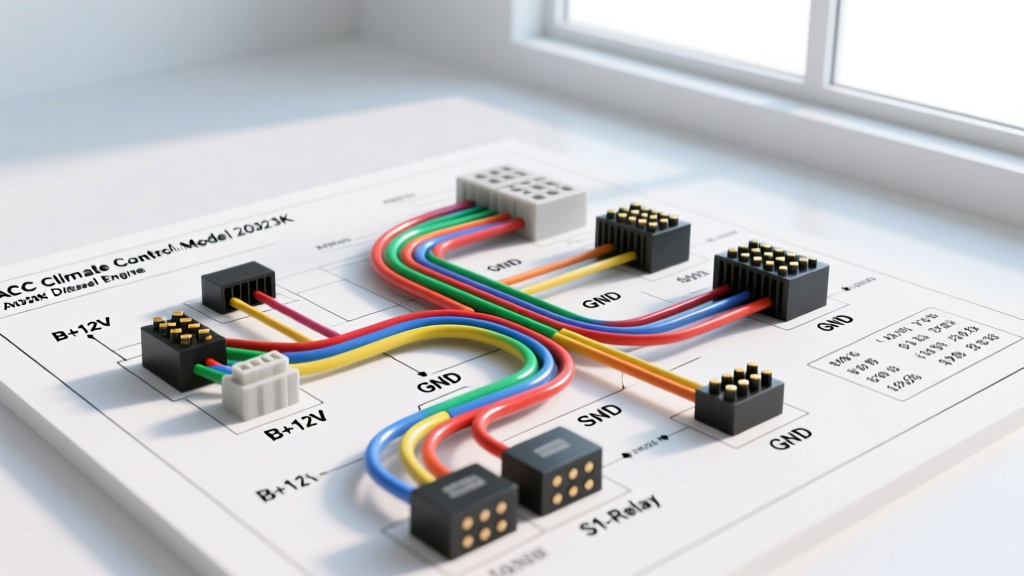
Introduction to the Model 20023K ACC Module in Diesel Swaps
When performing a diesel engine swap—whether dropping a 5.9L Cummins into a classic square-body truck or building a custom marine diesel application—managing cabin heat, air conditioning, and radiator cooling fans without a factory OEM ECU is a major hurdle. The ACC climate control Model 20023K diesel engine wiring diagram provides the blueprint for integrating a standalone Automatic Climate Control (ACC) and fan management module. This beginner-friendly guide breaks down the fundamentals of the 20023K controller, translating complex schematics into actionable, step-by-step wiring practices. By understanding the core logic of this module, you can safely manage high-amperage HVAC components and engine cooling systems while protecting your wiring harness from the harsh, high-vibration environment of a diesel engine bay.
Core Fundamentals: How the 20023K Controller Operates
Before cutting and crimping wire, it is crucial to understand how the Model 20023K makes decisions. The module acts as the brain for your thermal management system. It relies on Negative Temperature Coefficient (NTC) thermistors to monitor both engine coolant temperature (ECT) and cabin ambient temperature. As the temperature of the diesel engine rises, the electrical resistance of the NTC sensor drops. The 20023K reads this resistance change and triggers internal solid-state drivers to send a 12V signal to external ISO relays, which in turn power heavy-draw components like radiator fans and A/C compressors.
Because diesel engines generate significant Electromagnetic Interference (EMI) from high-amp alternators, glow plug controllers, and common-rail injection systems, the 20023K requires careful wire routing and shielding. A fundamental rule of diesel electrical work is to never run low-voltage sensor wires parallel to high-amperage power cables or fuel injector harnesses.
Model 20023K Pinout and Wire Color Reference Table
The 20023K utilizes a sealed 12-pin Weather-Pack connector to prevent moisture and oil intrusion. Below is the definitive pinout chart for your wiring diagram reference. Always adhere to the specified American Wire Gauge (AWG) ratings to prevent voltage drop and harness fires.
| Pin | Function | Wire Color | AWG Size | Technical Notes |
|---|---|---|---|---|
| 1 | Constant 12V Battery | Red | 10 AWG | Fuse at 30A. Connect directly to battery positive. |
| 2 | Ignition Switched 12V | Pink | 12 AWG | Must remain hot during 'Start' crank position. |
| 3 | Chassis / Engine Ground | Black | 10 AWG | Ring terminal directly to engine block or chassis. |
| 4 | ECT Sensor Signal | Light Green | 18 AWG | Use shielded twisted pair (STP) to block diesel EMI. |
| 5 | Sensor Ground | Black/White | 18 AWG | Dedicated clean ground back to module (Pin 3). |
| 6 | Cabin Temp Sensor | Yellow | 18 AWG | Route through firewall away from HVAC heater core. |
| 7 | HVAC Blower Relay Trigger | Blue | 14 AWG | Triggers external 40A relay for cabin blower motor. |
| 8 | Rad Fan 1 (Low Speed) | Brown | 14 AWG | Ground-side trigger for standard Bosch-style relay. |
| 9 | Rad Fan 2 (High Speed) | Orange | 14 AWG | Engages when ECT exceeds high-threshold limit. |
| 10 | A/C Compressor Clutch | Light Blue/Black | 14 AWG | Includes internal low-pressure safety cut-off logic. |
| 11 | CAN-H (Optional) | White | 20 AWG | For digital dash integration (e.g., Holley/AEM). |
| 12 | CAN-L (Optional) | White/Black | 20 AWG | Terminate with 120-ohm resistor if end of network. |
Power, Ground, and Ignition Circuits
Diesel starter motors pull massive amperage (often 600+ amps), causing severe voltage sag across the vehicle's electrical system during cranking. If your Model 20023K ignition feed (Pin 2) is wired to a thin 16 AWG wire or a circuit that drops to 8 volts during cranking, the module will reboot, killing your HVAC and cooling fans exactly when the engine is starting. To prevent this, wire Pin 2 to a true "Run" circuit that maintains voltage, or install a diode-and-capacitor delay circuit to keep the module powered through the crank cycle. For Pin 3 (Ground), never rely on sheet metal screws. Use a 10 AWG wire with a heavy-duty ring terminal bolted directly to the diesel engine block or a dedicated chassis ground stud, torqued to 15 lb-ft with star washers to bite through paint and powder coating.
Sensor Inputs and Fan Relay Outputs
The sensor circuits (Pins 4, 5, and 6) operate on a 5V reference logic. Because diesel engine bays are electrically noisy, you must use shielded cable for these 18 AWG wires. Connect the shield drain wire to the module ground (Pin 5) only at the module end to prevent ground loops. For the relay outputs (Pins 7, 8, 9, and 10), the 20023K uses internal solid-state switches to provide a ground path to your external relays. Critical Expert Tip: Always use external relays equipped with internal flyback diodes (or add a 1N4004 diode across the relay coil pins 85 and 86). When a relay coil de-energizes, it sends a high-voltage spike backward through the wiring. Without a flyback diode, this spike will instantly destroy the 20023K's internal driver transistors.
Step-by-Step Wiring Guide for Beginners
- Bench Test and Prep: Before installing the module in the vehicle, connect Pins 1, 2, and 3 to a 12V bench power supply. Use a multimeter to verify that the module powers up and that the output pins switch to ground when simulating temperature changes with a potentiometer.
- Route Power and Ground: Run your 10 AWG Red and Black wires directly to the battery and engine block. Keep these heavy-gauge wires at least 6 inches away from the exhaust manifold, turbocharger, and high-pressure fuel lines. Use split-loom tubing and high-temperature Tesa tape to protect against diesel engine bay heat.
- Deploy the Thermistors: Install the ECT sensor into a brass sensor bung welded into the radiator inlet or engine block water jacket. Do not use aluminum or steel bungs, as they can cause galvanic corrosion and alter the sensor's resistance reading over time.
- Build the Relay Harness: Mount a heavy-duty relay block near the radiator fans. Use 10 AWG wire for the relay's high-amperage power feeds (Pins 30 and 87 on the relay) and 14 AWG wire for the trigger signals coming from the 20023K module.
- Crimp and Seal: Use a proper ratcheting crimp tool for all Weather-Pack terminals. Apply dielectric grease to the connector cavities to prevent moisture ingress and corrosion, which is especially critical in off-road or marine diesel applications.
Common Troubleshooting & Failure Modes
Even with a perfect wiring diagram, real-world diesel environments can cause gremlins. Here is a diagnostic decision tree for common 20023K issues:
- Symptom: Radiator fans cycle rapidly on and off (short-cycling).
Cause: EMI interference on the ECT sensor wire or a poor sensor ground.
Fix: Verify shielded wire is used. Add a 0.1µF ceramic capacitor across the sensor signal and ground pins at the module to filter out high-frequency alternator noise. - Symptom: A/C compressor clutch will not engage, but cabin blower works.
Cause: The 20023K has an internal safety lockout if it detects engine load or incorrect refrigerant pressure.
Fix: Check your external binary/trinary A/C pressure switch. Ensure the module's Pin 10 is wired through the pressure switch before reaching the compressor clutch relay. - Symptom: Module resets and loses cabin temperature settings during engine crank.
Cause: Voltage drop on the Ignition feed (Pin 2).
Fix: Install a 12V automotive relay on the ignition feed, triggered by the starter solenoid's 'I' terminal, to maintain a dedicated 12V feed to the module while the starter is engaged.
Authoritative Resources & Further Reading
To deepen your understanding of automotive electrical standards and thermal management, consult the following authoritative resources:
- SAE International J1128 Standard: The definitive guide on low-tension primary cable specifications, including insulation temperature ratings and AWG current-carrying capacities essential for diesel engine bays.
- Bosch Motorsport Wiring Guidelines: Excellent reference material for understanding relay coil suppression, flyback diodes, and proper crimping techniques in high-vibration motorsport and heavy-duty diesel environments.
- ASHRAE Handbook of HVAC Systems: While aimed at commercial buildings, ASHRAE's fundamentals on NTC thermistor logic and refrigerant pressure-temperature relationships are highly applicable to custom automotive A/C retrofits.
By following this ACC climate control Model 20023K diesel engine wiring diagram guide and respecting the fundamental laws of automotive electricity, you will build a robust, reliable thermal management system capable of surviving the harshest diesel environments.