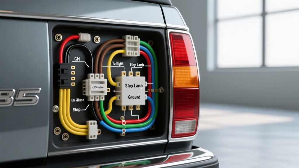
Understanding the 1985 El Camino Taillight Circuit
If you are diving into the world of classic automotive electrical systems, the 1985 Chevrolet El Camino is one of the most forgiving and educational platforms you can work on. As part of General Motors' legendary G-Body lineage, the 1985 model year sits in a sweet spot: it utilizes straightforward, analog 12V DC wiring without the complex multiplexed CAN-bus networks found in modern vehicles. However, 'simple' does not mean 'basic.' To successfully troubleshoot, repair, or upgrade your rear lighting, you must understand how GM engineered the circuit to flow from the battery, through the firewall bulkhead connector, down the driver-side frame rail, and into the rear tailgate harness.
This beginner-friendly guide breaks down the 1985 El Camino taillight wiring diagram into actionable fundamentals. We will cover the exact OEM wire color codes, American Wire Gauge (AWG) specifications, bulb configurations, and the unique GM steering column interlock system that trips up many novice mechanics.
1985 El Camino Taillight Wire Color Codes & Functions
The rear lighting harness on a 1985 El Camino branches off the main chassis harness near the rear crossmember. Because the El Camino is a coupe-utility, the final stretch of the harness must flex every time you open the trunk or bed cover, making this specific area a prime candidate for copper fatigue and broken wires. Below is the factory GM color-code matrix for the rear taillight circuits.
| OEM Wire Color | AWG Size | Circuit Function | Power Source / Routing |
|---|---|---|---|
| Brown | 18 AWG | Tail / Running / Marker Lights | Headlight Switch -> Firewall Bulkhead -> Rear Harness |
| Yellow | 18 AWG | Left Stop & Turn Signal | Brake Switch -> Turn Signal Switch -> Rear Harness |
| Dark Green | 18 AWG | Right Stop & Turn Signal | Brake Switch -> Turn Signal Switch -> Rear Harness |
| Light Green | 18 AWG | Reverse / Backup Lights | Neutral Safety / Backup Switch on Steering Column |
| Black | 16 AWG | Chassis Ground | Spliced to main ground bus -> Sheet metal screw on tail panel |
According to the SAE J1128 Low Tension Primary Cable Standard, 18 AWG stranded copper wire is rated for up to 10 amps of continuous current, which is more than sufficient for the incandescent bulbs used in the El Camino's rear housings. The insulation is typically PVC or cross-linked polyethylene (XLPE), designed to withstand the high heat and road debris exposure under the vehicle.
Bulb Specifications and the Dual-Filament Concept
The 1985 El Camino uses standard bayonet-style push-in sockets. For the primary stop/tail functions, the factory specification calls for the 1157 bulb. For the reverse lights, it uses the single-filament 1156 bulb.
As a beginner, it is vital to understand how the 1157 dual-filament bulb works in conjunction with federal regulations. The FMVSS 108 Lighting Standards mandate specific candlepower outputs for both running lights and brake lights to ensure following drivers can distinguish between a vehicle simply driving at night and one that is actively braking. The 1157 bulb achieves this by housing two separate tungsten filaments inside the same glass envelope:
- Tail/Running Filament: Lower wattage (approx. 8W), dimmer glow, activated by the Brown wire.
- Stop/Turn Filament: Higher wattage (approx. 27W), much brighter, activated by the Yellow or Dark Green wire.
The Offset Pin Trap
One of the most common mistakes beginners make is forcing an 1157 bulb into the socket incorrectly. The bayonet base of an 1157 bulb features offset pins—one pin is slightly higher than the other. This is a deliberate mechanical keyway designed to ensure the correct filament aligns with the correct contact pad inside the socket. If you force it in backwards, your bright brake light will act as your dim running light, and your dim running light will blind drivers behind you when you tap the brakes. Always align the pins with the staggered slots on the socket housing.
The GM Steering Column Interlock: A Beginner's Guide
If you are reading a 1985 El Camino taillight wiring diagram, you will quickly notice a quirk in the GM G-Body electrical architecture: the brake lights and the turn signals share the exact same wire and the exact same bulb filament.
How does the car prevent the brake light from staying solid when you are trying to flash the turn signal? The answer lies inside the steering column. When you press the brake pedal, 12V power travels up to the turn signal switch located just beneath the steering wheel. If the turn signal lever is in the neutral (center) position, the switch passes that 12V straight back to both the Yellow and Dark Green wires, illuminating both brake lights.
However, if you engage the left turn signal, the mechanical cam inside the steering column physically disconnects the brake power to the Yellow wire, and instead routes pulsing power from the flasher relay to the Yellow wire. This is why a faulty turn signal switch, a stuck hazard button, or a melted connector at the base of the steering column will often result in brake lights that do not work, even though the third brake light (if equipped) or the front turn signals work perfectly. When troubleshooting rear lighting on an '85 El Camino, always verify the steering column switch before tearing apart the rear harness.
Grounding: The Hidden Culprit of G-Body Electrical Gremlins
The Black 16 AWG ground wire is the anchor of your entire taillight circuit. In a 1985 El Camino, the rear harness grounds to the inner steel skin of the rear tailgate or the bedside inner fender via a simple sheet metal screw. After nearly four decades of exposure to moisture, road salt, and temperature fluctuations, the steel behind that screw is almost certainly compromised by rust.
Rust is an electrical insulator. A poor ground creates high resistance, which leads to a phenomenon called backfeeding. If the ground path is weak, current from the bright brake filament will seek an alternative path to ground by flowing backward through the dim tail filament, across the Brown wire, and into the opposite side's tail light housing. The result? You press the brake pedal, and both taillights light up dimly, but the actual bright brake lights never engage. Always sand the grounding point down to bare, shiny metal and apply dielectric grease to prevent future oxidation.
Step-by-Step Troubleshooting for Beginners
Before replacing parts, use a digital multimeter (DMM) to diagnose the circuit logically. Consult resources like Haynes Automotive Repair Manuals for specific fuse block layouts, but follow these universal diagnostic steps for the '85 El Camino:
- Check the 'TAIL' Fuse: Located in the glass fuse block under the driver's side dash. If the Brown wire is shorted to ground anywhere along the frame rail, this 20A fuse will blow, killing all running lights.
- Test for Voltage at the Socket: Set your DMM to DC Volts. Place the black probe on a known good chassis ground (like the bare metal of the bumper) and the red probe on the socket contacts. You should see ~12.6V with the headlights on (Brown contact) and ~12.6V when the brake is pressed (Yellow/Green contact).
- Perform a Voltage Drop Test on the Ground: If you have voltage at the socket but the bulb won't light, your ground is bad. Place your DMM red probe on the negative battery terminal and the black probe on the metal base of the bulb socket while the circuit is active. A reading above 0.2V indicates excessive resistance in the Black ground wire.
- Inspect the Trunk Hinge Flex Zone: Visually inspect the harness where it transitions from the fixed body to the moving trunk/bed area. The 18 AWG stranded copper work-hardens over time and snaps inside the insulation. Peel back the loom and tug gently on the wires to check for hidden breaks.
A Note on LED Upgrades and Hyperflashing
Many beginners restoring an El Camino want to upgrade to modern 1157 LED bulbs for a brighter, whiter look. While the physical fitment and wiring remain identical, you must understand the thermal-electrical relationship of the original flasher relay. The factory thermal flasher unit under the dash relies on the specific amperage draw (heat) of the incandescent bulbs to bend the internal bi-metallic strip and create the 'click-click' flashing rhythm. Because LEDs draw less than 10% of the amperage of halogen bulbs, the flasher relay will not heat up enough to cycle, resulting in a rapid 'hyperflash' or a solid light. To fix this without cutting wires, simply swap the factory thermal relay for an electronic LED-compatible flasher relay (often designated as an EL12 or CF13 style for GM columns), which uses a microchip to time the flashes regardless of the circuit's amperage draw.