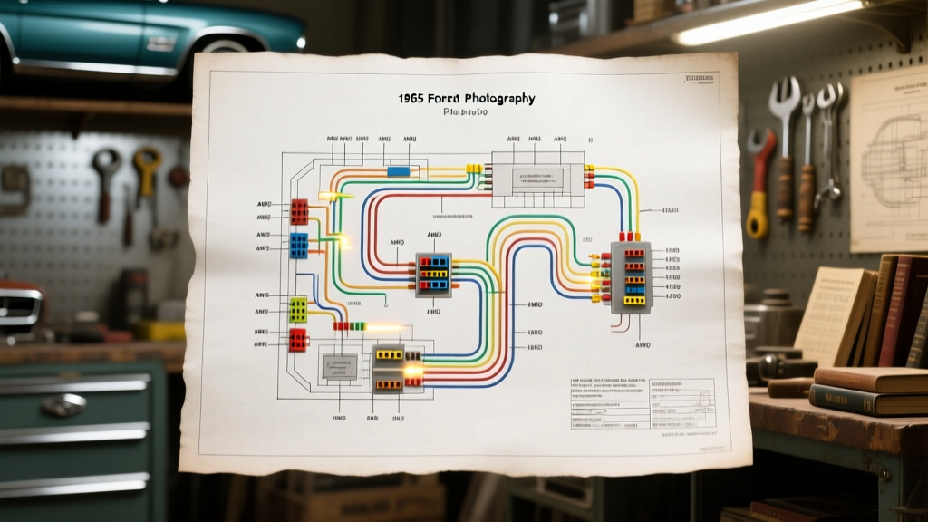
The Reality of Rewiring a First-Generation Mustang
When restoring or troubleshooting a first-generation Ford, possessing an accurate 1965 Mustang wiring diagram is only the first step. The true bottleneck for most DIY restorers and professional shops alike lies in the cost of materials and the specialized tooling required to execute the repairs to OEM specifications. Unlike modern vehicles utilizing sealed, modular connector blocks, the 1965 Mustang relies on a complex web of bullet connectors, early Packard Electric terminals, and early PVC primary wires. This comprehensive analysis breaks down the exact financial and tooling requirements needed to properly service, repair, or replace the electrical system of a 1965 Ford Mustang, ensuring your build is both safe and historically accurate.
Decoding the Core Circuits: AWG and Color Code Specifications
Ford's standard color-coding system in 1965 was highly logical, but decades of heat, vibration, and previous owner repairs often obscure the original diagram's intent. Before purchasing materials, you must map the critical high-amperage circuits. The most notorious is the ammeter loop. The 1965 Mustang routes the entire alternator output through the dash ammeter via a 10 AWG Black/Yellow wire. According to M.A.D. Enterprises, this specific circuit design is a known fire hazard if the 10 AWG wire frays or the ammeter posts loosen, creating high resistance and extreme heat. Understanding the exact AWG requirements prevents voltage drop and potential electrical fires.
| Circuit Function | OEM Ford Color Code | AWG Size | Connector Type | Est. Repair Cost |
|---|---|---|---|---|
| Alternator Output / Ammeter Loop | Black w/ Yellow Tracer | 10 AWG | Ring Terminal / Stud | $18.50 |
| Headlight Feed (Main) | Red w/ Black Tracer | 12 AWG | Packard 56-Series | $24.00 |
| Ignition Switch to Coil | Red w/ Green Tracer | 14 AWG | Bullet Connector | $9.00 |
| Starter Solenoid Trigger | Red w/ Blue Tracer | 14 AWG | Push-On Spade | $6.50 |
| Fuel Tank Sender Unit | Black w/ White Tracer | 18 AWG | Bullet Connector | $5.00 |
Mandatory Tool Requirements for OEM-Spec Repairs
You cannot reliably crimp 1960s Ford terminals with a generic hardware store tool. The 1965 Mustang utilizes specific terminal families that require precise deformation to ensure a gas-tight connection. Investing in the correct tooling upfront saves hours of diagnostic frustration later.
1. Delphi/Packard 56-Series Crimpers
The firewall bulkhead connector and the dash harness connections on a 1965 Mustang heavily utilize the Packard Electric 56-series flat blade terminals. Standard crimpers will crush the terminal wings, leading to loose pins that arc and melt the plastic housing. You must use a dedicated ratcheting crimper designed for Packard 56 terminals (such as the Delphi 12085111 or equivalent aftermarket tool). Budget approximately $85 to $120 for a high-quality ratcheting crimper that ensures the wire crimp and insulation crimp are formed simultaneously to OEM tolerances.
2. Bullet Connector Soldering & Heat Shrink Kit
While Ford used bullet connectors extensively for lighting and sender units, simple crimping is often insufficient for the undercarriage due to moisture ingress. Professional restorers solder the bullet splices and seal them with dual-wall, adhesive-lined heat shrink tubing. A temperature-controlled soldering station (40W-60W) and a supply of 3M dual-wall heat shrink will cost around $65, but it guarantees that your taillight and reverse light circuits will not corrode from the inside out.
3. Diagnostic Testing Equipment
To verify the 1965 Mustang wiring diagram against the physical harness, a standard multimeter is not enough. You need a Digital Multimeter (DMM) with a low-impedance mode (like the Fluke 87V, approx. $400) to bleed off phantom voltages caused by corroded 50-year-old copper. Alternatively, a Power Probe III (approx. $250) allows you to inject power and ground directly into the Packard 56 terminals to test wiper motors and blower motors without back-probing and damaging the fragile vintage wire insulation.
Wire Insulation and Loom Material Costs
When referencing the 1965 Mustang wiring diagram for a full rewire, the copper is only half the expense. The insulation and loom materials dictate both the safety and the concours-correctness of the vehicle. Early 1965 models utilized PVC-insulated wire, which becomes brittle and cracks when exposed to modern engine bay temperatures. When sourcing replacement wire, it is highly recommended to upgrade to Cross-Linked Polyethylene (XLPE) insulation, which meets modern SAE J1128 standards for high-temperature automotive primary cable. XLPE wire costs roughly 15% more than standard PVC wire, adding about $45 to a full harness material budget, but it provides superior resistance to under-hood heat and abrasion.
Furthermore, Ford used specific non-adhesive friction tape and corrugated split-loom in various areas. Budget $30 for harness wrapping tape (like Tesa 51036) to properly bind the engine bay harnesses, ensuring they look correct and are protected from the exhaust manifolds.
Cost Analysis: OEM Restoration vs. Restomod Upgrades
Budgeting for a 1965 Mustang electrical overhaul depends entirely on your end goal. A concours-correct restoration demands vastly different financial resources compared to a restomod build featuring modern EFI, electric cooling fans, and high-output audio.
Path A: Concours-Correct OEM Restoration
Sourcing a licensed OEM reproduction harness from established suppliers like Osborn Reproduction typically costs between $350 and $450 for the main dash and under-hood harnesses. However, you must also budget for correct Ford-spec cloth-braided loom, OEM-style glass fuse blocks, and date-coded reproduction bulbs. You are strictly following the 1965 Mustang wiring diagram, retaining the factory ammeter and the original 35-amp alternator circuit. Total material cost for a factory-correct refresh: $600 to $850.
Path B: The Restomod / High-Amperage Upgrade
If your 1965 Mustang is equipped with a modern 130A 3G alternator, electric cooling fans, and an EFI system, the factory 10 AWG and 12 AWG circuits will melt under the load. You must abandon the factory diagram's ammeter loop and upgrade to a 4 AWG or 2 AWG main power cable routed directly to a mega-fuse and high-amperage relay block. A universal Restomod harness (e.g., Painless Performance or Ron Francis) costs $450 to $650. This includes modern blade fuses, pre-terminated EFI relays, and heavy-gauge charging wires. Add an additional $200 for 2 AWG battery cables and ANL fuse blocks. Total material cost: $700 to $1,000.
Common 1965 Mustang Wiring Failure Modes & Diagnostic Costs
Even with a perfect diagram, certain areas of the 1965 Mustang are prone to specific failure modes that require targeted diagnostic time and replacement parts.
The C4 Automatic Neutral Safety Switch
For Mustangs equipped with the C4 automatic transmission, the starter solenoid trigger wire (14 AWG Red/Blue) routes through the neutral safety switch located on the transmission case. A common failure mode is the internal contacts of the switch corroding, resulting in a 'no-crank' condition. Diagnosing this requires bypassing the switch with a jumper wire. If the starter engages, the switch is faulty. Replacement switches cost around $25, but the labor to drop the transmission crossmember and align the switch pin can add $150 to a shop bill.
Steering Column Turn Signal Cam
The 1965 turn signal switch is integrated into the steering column cam and handles multiple circuits simultaneously, including the brake lights and turn signals (utilizing 14 AWG Green/White and White/Blue wires). The copper contacts inside the plastic cam wear down, causing the brake lights to stay on or the turn signals to fail on one side. A replacement turn signal cam kit costs $35, but requires compressing the steering wheel lock plate and carefully routing the harness down the column without pinching the 18 AWG horn ring wire.
Final Expert Recommendations
Successfully navigating the 1965 Mustang wiring diagram requires more than just reading lines on a page; it requires an investment in proper terminal crimpers, high-temperature XLPE wire, and a clear understanding of your vehicle's amperage demands. Whether you are preserving a pristine 289ci coupe with an OEM harness or wiring a 5.0L Coyote-swapped fastback, matching your tooling and budget to the specific requirements of the 1965 Ford electrical architecture is the only way to ensure reliable, fire-free operation for decades to come.