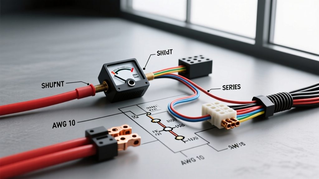
The Evolution of Automotive Current Measurement
When restoring a classic muscle car or building a modern restomod, upgrading the charging system is a mandatory step. Swapping a factory 40-amp generator or early 10SI alternator for a modern 120-amp+ one-wire alternator fundamentally changes the electrical topology of the vehicle. This is where selecting the correct wiring diagram for ammeter integration becomes a critical safety and performance decision. Routing 120+ amps of current through the dashboard of a 1969 Chevelle or 1970 Mustang using factory methods is a guaranteed recipe for a bulkhead connector fire.
As an automotive electrical specialist, I frequently evaluate two primary ammeter architectures for classic and custom vehicles: the traditional Series (In-Line) Ammeter and the modern Shunt-Type Ammeter. This guide compares these two systems, provides the technical schematics for both, and outlines the exact AWG specifications, crimping standards, and routing protocols required for a safe, high-fidelity installation.
Series (In-Line) Ammeters: The Classic GM Architecture
In a series ammeter configuration, 100% of the alternator’s output current flows directly through the gauge on the dashboard. This was the standard engineering practice for General Motors A-Body (Chevelle, GTO) and F-Body (Camaro, Firebird) vehicles from 1968 through 1972. The ammeter essentially acts as a low-resistance shunt built into the gauge movement, measuring the voltage drop across an internal coil.
Classic GM Series Wiring Schematic & Specifications
- Main Power Path: Alternator BAT terminal → 10 AWG Black wire → Horn Relay Bus Bar → 10 AWG Red wire → Firewall Bulkhead Connector → Ammeter → Bulkhead Connector → Dash Harness to Ignition Switch.
- Wire Specification: 10 AWG SAE J1128 Type SXL (Cross-linked polyethylene) to handle under-hood temperatures up to 125°C.
- Connector Type: Packard 56-series male and female terminals housed in the factory firewall bulkhead block.
- Max Safe Current: ~45 Amps continuous.
The Fatal Flaw of Series Ammeters in Restomods
While a series ammeter provides a highly responsive, real-time readout of charge and discharge states, it is fundamentally incompatible with modern high-output alternators. If your upgraded CS130D or Powermaster alternator pushes 90 amps through a 45-year-old Packard 56 bulkhead connector, the resistance at the crimp points will generate massive heat. According to Mad Electrical's technical archives, bulkhead fires are the leading cause of electrical loss in classic GM vehicles running high-amp series ammeter loops. If you are running an alternator over 60 amps, you must bypass the dash and use a shunt system.
Shunt-Type Ammeters: The Modern High-Amp Solution
To safely measure high current without routing heavy-gauge battery cables through the passenger compartment, modern aftermarket manufacturers like Auto Meter and Dakota Digital utilize an external shunt. A shunt is a precision resistor placed in the main battery cable. By measuring the millivolt (mV) drop across the shunt, the gauge calculates the amperage using Ohm’s Law (I = V/R).
Auto Meter 5284 Shunt Ammeter Wiring Schematic
The Auto Meter 5284 is an industry-standard 500-amp shunt ammeter. The heavy current stays under the hood, while only low-voltage signal wires enter the cabin.
- Heavy Current Path (Under Hood): Alternator BAT terminal → 4 AWG XLPE Cable → Shunt Terminal 'A'. Shunt Terminal 'B' → 4 AWG XLPE Cable → Battery Positive Terminal (or main distribution block).
- Signal Path (To Dash): Shunt Signal Terminal 1 (+) and Terminal 2 (-) → 18 AWG Shielded Twisted-Pair wire → Gauge Backlight and Signal Pins.
- Shunt Specifications: Rated for 500 Amps continuous, yielding a 50mV voltage drop at full scale.
- Overcurrent Protection: A Class T or ANL fuse (rated slightly above max alternator output, e.g., 150A) must be installed on the 4 AWG cable within 7 inches of the battery positive terminal, per SAE J1128 and ABYC E-11 standards.
Head-to-Head Comparison Matrix
| Feature | Series (OEM GM Style) | Shunt (Auto Meter 5284) |
|---|---|---|
| Max Safe Amperage | 45A - 60A | 500A |
| Dash Wire Gauge | 10 AWG (Full Current) | 18 AWG (Signal Only) |
| Fire Hazard Risk | High (if alternator >60A) | Negligible |
| Alternator Ripple Rejection | Excellent (Analog coil) | Requires twisted-pair shielding |
| Installation Complexity | Moderate (Bulkhead crimping) | High (Shunt mounting, 4 AWG lugs) |
Step-by-Step Selection & Wiring Best Practices
Choosing the right wiring diagram for ammeter integration depends entirely on your alternator output and firewall topology. Follow these expert-level installation protocols to ensure longevity and accuracy.
1. Wire Selection and Insulation Types
Never use standard PVC-insulated wire (Type GXL or TWP) under the hood near exhaust manifolds. Always specify SAE J1128 Type SXL (Cross-linked polyethylene) for the 4 AWG main shunt cables and the 10 AWG series loops. SXL insulation withstands continuous temperatures of 125°C and resists melting against sharp metal edges.
2. The Art of the Packard 56 Crimp (Series Systems)
If you are retaining a factory series ammeter for a numbers-matching restoration (and limiting your alternator to a 60A 10SI unit), you must use the correct crimping tool. The Packard 56 terminal requires an open-barrel, four-indent crimper (such as the Delphi 12094428 or equivalent). Using a generic hex-crimper or pliers deforms the terminal, creating a high-resistance joint that will melt the bulkhead plastic under load.
3. Signal Wire Routing and EMI Rejection (Shunt Systems)
Modern high-output alternators generate significant AC ripple and electromagnetic interference (EMI). The 50mV signal traveling from the shunt to the Auto Meter 5284 gauge is highly susceptible to this noise, which can cause the needle to flutter wildly. To combat this, the 18 AWG signal wires must be a twisted pair (twisting the wires 4 to 6 times per inch). This creates a common-mode choke effect that rejects alternator EMI. Route these signal wires away from HEI distributor coils, MSD ignition boxes, and alternator stator wires.
4. Shunt Mounting and Thermal Drift
Shunts are calibrated at a specific ambient temperature (usually 20°C). Mounting the shunt directly on top of the engine block or near exhaust headers will cause thermal drift, resulting in inaccurate amperage readings. Mount the shunt on the inner fender well or a dedicated firewall distribution block, ensuring adequate airflow for convective cooling.
Troubleshooting Common Ammeter Wiring Faults
Even with the correct schematic, real-world variables can introduce faults. Use this diagnostic decision tree to resolve common issues.
Symptom: Ammeter Reads Zero or Fluctuates Wildly at Idle
- Cause 1 (Shunt Systems): Alternator AC ripple interfering with the mV signal. Fix: Verify signal wires are tightly twisted. Install a 0.1µF ceramic capacitor across the gauge signal terminals to filter high-frequency noise.
- Cause 2 (Series Systems): High resistance in the bulkhead connector. Fix: Pull the bulkhead, inspect for green corrosion or melted plastic. Clean terminals with electrical contact cleaner and apply dielectric grease.
Symptom: Ammeter Pegs to 'Discharge' When Engine is Running
- Cause: Reversed polarity at the shunt or gauge. Current is flowing backward through the measurement circuit relative to the gauge's internal logic. Fix: Swap the 18 AWG signal wires at the back of the gauge (Terminal 1 and Terminal 2). Do not swap the heavy 4 AWG battery cables.
Symptom: Melted Wiring Harness or Burnt Smell in Cabin
- Cause: Series ammeter overloaded by a high-amp alternator. Fix: Immediately disconnect the battery. You must abandon the series loop. Convert the vehicle to a shunt-style ammeter or a voltmeter, and run a dedicated 4 AWG charge wire from the alternator directly to the battery positive terminal, bypassing the dash entirely.
For further reading on heavy-gauge cable termination and alternator charge-wire routing, refer to the Auto Meter Technical Installation Manuals for precise torque specifications on shunt terminal nuts (typically 45-50 in-lbs to prevent stripping the copper bus bar).
Final Verdict: Which Diagram Should You Choose?
If you are performing a concourse restoration on a 1969 Z/28 or SS396 and retaining the factory 40-amp charging system, the Series Ammeter wiring diagram is historically accurate and safe when executed with proper Packard 56 tooling. However, for 95% of modern builds, LS swaps, and restomods utilizing 100A+ alternators, the Shunt-Type Ammeter wiring diagram is the only safe, reliable choice. By keeping heavy current under the hood and utilizing twisted-pair signal routing, you protect your vehicle from catastrophic electrical fires while gaining precise, real-time insight into your charging system's health.