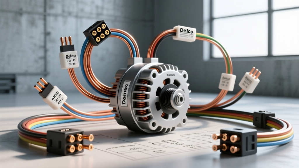
Decoding the Delco Remy Alternator Wiring Diagram: Beyond the Basics
The Delco Remy 10SI and 12SI alternators remain the backbone of classic GM charging systems and are the gold standard for custom automotive, marine, and agricultural conversions. However, interpreting a Delco Remy alternator wiring diagram correctly requires more than just bolting on a battery cable and hoping for the best. To achieve a factory-grade, reliable charging system, you must invest in the correct termination tools, high-temperature wire, and precision testing equipment.
Many enthusiasts opt for a cheap "1-wire" conversion to save money and simplify the engine bay. While a 1-wire setup (connecting only the main BAT terminal and jumping Terminal 1 to the BAT post) costs less upfront, it sacrifices voltage regulation accuracy. A proper 3-wire harness routes the voltage sense wire (Terminal 1) directly to the battery positive terminal or main distribution block. This allows the internal solid-state voltage regulator to compensate for voltage drop across the main power cable, ensuring your battery actually receives 14.2V under heavy electrical loads. This guide breaks down the exact costs, tooling requirements, and technical specifications needed to wire a Delco SI-series alternator properly from a cost-and-tool analysis perspective.
Essential Tool Requirements for a Factory-Grade Harness
Automotive electrical failures rarely occur in the middle of a wire; they happen at the termination points. Vibration, heat, and moisture wick into poorly crimped connections, leading to resistance, voltage drops, and eventually, a melted connector or a dead battery. To build a harness that mirrors OEM Delco Remy standards, you need specialized tooling.
1. Ratcheting Crimping Tools (Non-Negotiable)
Standard slip-joint pliers are unacceptable for alternator wiring. You must use a ratcheting crimper designed for open-barrel or insulated terminals. For the Delco 3-pin connector pigtail, you need a crimper that handles 22-16 AWG insulated terminals. The IWISS IWS-3220M or a Knipex 48 00 J3 ensures the terminal wraps tightly around the wire strands and the insulation grip secures the jacket, providing the necessary pull-out resistance to survive engine bay harmonics.
2. Adhesive-Lined Heat Shrink & Torch
Standard electrical tape will unravel in the 105°C+ environment of an engine bay. You must use dual-wall, adhesive-lined heat shrink tubing with a 3:1 shrink ratio. When heated with a butane micro-torch, the inner meltable adhesive wall flows into the wire strands, creating a waterproof seal that prevents copper oxidation and green rot.
3. Diagnostic Testing Equipment
A basic multimeter is insufficient for diagnosing alternator ripple or precise voltage drops. You need a True-RMS digital multimeter (like the Fluke 87V or Power Probe PD400) capable of measuring millivolts (mV) to perform accurate voltage drop testing across the main charge cable and the ground circuit.
Material Cost Breakdown: 3-Wire Harness Rebuild
Building a custom, high-reliability 3-wire harness for a Delco 10SI/12SI alternator is surprisingly cost-effective compared to buying a pre-made, mass-produced harness that often uses undersized wire and cheap vinyl insulation. Below is a realistic cost analysis for sourcing premium materials.
| Component / Material | Specification | Estimated Cost (USD) |
|---|---|---|
| Delco 3-Pin Pigtail Connector | OEM-style Packard connector (e.g., Standard Motor Products PT129) | $8.50 - $14.00 |
| Main Charge Cable (BAT) | 1/0 AWG or 4 AWG SXL (Cross-linked) Copper | $1.50 / ft |
| Terminal 1 (Sense) Wire | 12 AWG SXL Copper (Red) | $0.60 / ft |
| Terminal 2 (Exciter) Wire | 12 AWG SXL Copper (White or Brown) | $0.60 / ft |
| Main Ring Terminals | Heavy-duty tinned copper, 3/8" or 5/16" stud, 2:1 adhesive shrink | $4.00 (pack) |
| Inline Fuse Holder (Main) | ANL or Mega Fuse Holder with 120A-150A Fuse | $18.00 - $25.00 |
| Exciter Circuit Resistor | 1/2 Watt, 470-Ohm (if using LED dash light) | $0.15 |
| Total Estimated Material Cost | For a complete, premium 3-wire harness rebuild | $45.00 - $65.00 |
Note: Prices fluctuate based on copper markets and vendor. SXL wire is mandatory; do not substitute with PVC-insulated primary wire, which will melt against exhaust headers.
Wire Gauge (AWG) and Color Code Specifications
When reviewing your Delco Remy alternator wiring diagram, adhering to the correct American Wire Gauge (AWG) and standard automotive color codes is critical for both performance and future troubleshooting. According to SAE J1128 standards for low-tension primary cable, wire sizing must account for both amperage and the physical length of the run to prevent excessive voltage drop.
| Terminal / Post | Function | Min. AWG Size | Standard Color Code | Routing Destination |
|---|---|---|---|---|
| BAT (Main Post) | Primary DC Output | 4 AWG (up to 80A) / 1/0 AWG (100A+) | Red (Heavy Duty) | Starter Solenoid or Main Distribution Bus (via Fuse) |
| Terminal 1 (Sense) | Voltage Regulation Feedback | 12 AWG | Red (Light) | Battery Positive Post or Main Ignition Bus |
| Terminal 2 (Exciter) | Rotor Field Excitation | 12 AWG | White or Brown | Ignition Switch (via Dash Indicator Bulb) |
The Critical Role of Terminal 1 (Voltage Sense)
The most common mistake made when wiring a Delco Remy alternator is routing Terminal 1 to the alternator's own BAT post. If you do this, the voltage regulator only senses the voltage at the back of the alternator. If the main charge cable has a 0.8V drop due to length, corrosion, or undersized wire, the battery will only receive 13.4V while the alternator thinks it is outputting a perfect 14.2V. By running a dedicated 12 AWG sense wire from Terminal 1 directly to the battery positive terminal, the regulator will automatically increase its output to compensate for the voltage drop in the main cable, ensuring the battery receives the full 14.2V.
Hidden Costs: The Excitation Circuit and LED Failures
Terminal 2 is the exciter terminal. The internal voltage regulator requires a small initial current draw (typically 150mA to 300mA) to "wake up" and begin charging. In factory GM vehicles, this current is drawn through the dash indicator (idiot) light bulb. When you turn the key to the "ON" position, 12V flows through the bulb, illuminating it, and into Terminal 2, exciting the rotor field. Once the alternator begins generating power, the voltage on both sides of the bulb equalizes, and the light turns off.
The LED Problem: If you are building a custom harness for a hot rod or tractor and decide to use a modern LED indicator light, you will run into a hidden cost and failure mode. LEDs draw virtually zero current. The Delco Remy regulator will not detect enough resistance to turn on, resulting in a "no-charge" condition until you rev the engine to 2,500+ RPM to force the alternator into self-excitation via residual magnetism.
The Fix: You must wire a standard 1/2-watt, 470-ohm resistor in parallel with your LED indicator light, or simply use a traditional 12V incandescent #194 bulb (which provides the correct 10-15 ohms of resistance). This costs less than a dollar but saves hours of frustrating diagnostic labor.
Validation: Voltage Drop Testing the Finished Harness
Once your Delco Remy alternator wiring diagram has been executed and the harness is loomed, you must validate the installation using a voltage drop test. This test is far more accurate than simply measuring the voltage at the battery.
- Main Charge Cable Test: Set your multimeter to DC Volts. Place the red probe on the alternator BAT post and the black probe on the battery positive terminal. Start the engine and turn on high-draw accessories (headlights, heater blower). The reading should be less than 0.2V. If it reads higher, your main cable is undersized, or your crimps have excessive resistance.
- Ground Circuit Test: Place the red probe on the battery negative terminal and the black probe on the alternator metal casing. Under load, the voltage drop must be less than 0.1V. If higher, you need to add a dedicated braided ground strap from the alternator case to the engine block or chassis.
Authoritative References & Further Reading
For deeper engineering specifications regarding Delco Remy SI-series alternators and automotive wiring standards, consult the following authoritative resources:
- SAE International: SAE J1128 - Low Tension Primary Cable Standard. Essential for understanding temperature ratings and AWG current capacities in engine bay environments.
- MAD Electrical: Alternator Tech: Delco 10-SI and 12-SI Wiring. Mark Hamilton's legendary technical breakdown of the internal regulator logic and 1-wire vs 3-wire performance paradigms.
By investing in the correct ratcheting crimpers, SXL high-temp wire, and understanding the precise logic of the 3-pin connector, you transform a basic Delco Remy alternator swap into a bulletproof, OEM-grade charging system that will reliably power high-amperage accessories for years to come.