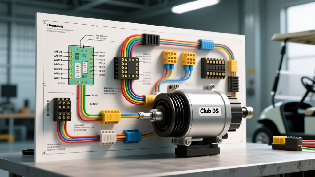
Understanding the Golf Cart Starter Generator Wiring Diagram
Understanding the golf cart starter generator wiring diagram requires moving beyond basic 12-volt automotive concepts and delving into dual-mode electromechanical systems. Unlike standard automotive applications where the starter motor and alternator are entirely separate components, gas-powered golf carts—most notably the Club Car DS and Precedent platforms equipped with the FE290 or Kawasaki FE350 engines—utilize a combined starter-generator unit. This advanced technical deep dive dissects the exact circuit topology, OEM wire color codes, AWG requirements, and voltage regulator feedback loops necessary to properly diagnose, rebuild, or upgrade your golf cart's charging and cranking system.
The Engineering Behind the Starter-Generator
A starter-generator operates on two distinct electromagnetic principles depending on the state of the engine. During the cranking phase, the unit functions as a series-wound DC motor. The ignition switch routes 12V DC power to the main solenoid, which bridges the high-amperage B+ circuit to the starter-generator's primary terminal. Simultaneously, the field coils are energized, creating a massive magnetic flux that turns the armature and engages the drive belt to spin the engine's flywheel.
Once the engine achieves self-sustaining combustion and the operator releases the key from the "Start" position to the "Run" position, the internal centrifugal switch or external voltage regulator alters the circuit topology. The unit transitions into a shunt-wound DC generator. The engine now drives the armature via the serpentine belt, cutting through the magnetic field to induce an alternating current, which is internally rectified to DC to recharge the 12V battery and power auxiliary accessories.
Terminal Identification and Pinout Specifications
Accurate interpretation of the golf cart starter generator wiring diagram hinges on proper terminal identification. Misrouting the DF (Field) and L (Exciter/Light) wires is the most common cause of catastrophic voltage regulator failure. Below is the definitive pinout specification for the standard 4-terminal Club Car / Kawasaki starter-generator.
| Terminal ID | Designation | Function | OEM Wire Color | AWG Size | Torque Spec |
|---|---|---|---|---|---|
| B+ | Battery Positive | Main High-Amp Power Input/Output | Red | 4 or 6 AWG | 90 in-lbs |
| DF | Dynamo Field | Field Coil Excitation & Regulation | Green | 16 AWG | 45 in-lbs |
| L | Light / Exciter | Charge Indicator & Initial Excitation | Yellow | 16 AWG | 45 in-lbs |
| E | Earth / Ground | Internal Case Ground Return | Black (or Bare) | 10 AWG | 120 in-lbs |
Ignition Switch and Solenoid Routing Logic
The cranking circuit is governed by a sequence of microswitches and heavy-duty contactors. When the ignition key is turned to "Start", 12V power flows from the battery positive terminal through a 15A inline fuse to the ignition switch. From the "Start" lug on the ignition switch, a 16 AWG blue wire routes to the coil of the main starter solenoid.
However, the solenoid will not engage unless the cart is in a valid drive state. The ground path for the solenoid coil is routed through the Forward/Reverse (F&R) microswitch assembly located under the seat. If the F&R lever is in the neutral safety position, the circuit remains open. When engaged in Forward or Reverse, the microswitch closes, providing the ground path to complete the solenoid coil circuit. The solenoid plunger pulls down, bridging the heavy 4 AWG cables from the battery directly to the B+ terminal on the starter-generator, initiating the cranking sequence.
Voltage Regulator Integration and the DF Circuit
The transition from cranking to charging is managed by the voltage regulator. In older Club Car DS models, this was a mechanical 4-terminal regulator; newer models utilize a solid-state 6-terminal module. The critical wire in this golf cart starter generator wiring diagram is the DF (Field) wire, typically green.
During cranking, the DF terminal receives full battery voltage to maximize magnetic flux and cranking torque. Once the engine is running, the voltage regulator monitors the system voltage via the B+ sense wire. If the battery voltage drops below 13.8V, the regulator pulses the DF circuit to ground, increasing the magnetic field strength and boosting alternator output. If system voltage exceeds 14.4V, the regulator introduces resistance or cuts the DF ground path entirely, preventing overcharging and battery outgassing.
Wire Gauge (AWG) and Routing Standards
Adhering to SAE J1128 standards for low-tension primary cables is non-negotiable when executing this wiring diagram. The B+ circuit experiences current spikes exceeding 250 amps during initial cranking in cold conditions or when the engine is under high compression. Using undersized wiring will result in severe voltage drop, slow cranking speeds, and melted insulation.
- B+ and Main Ground: Must be 4 AWG or 6 AWG stranded copper with high-strand-count silicone or EPDM insulation to withstand engine bay heat and vibration.
- Solenoid to Starter-Gen B+: 4 AWG minimum.
- Ignition and Regulator Sense Wires: 14 AWG to 16 AWG is sufficient, as these carry less than 2 amps of continuous current.
All connections must be terminated with tinned copper ring terminals, crimped with a hex-crimper, and sealed with adhesive-lined heat shrink to prevent galvanic corrosion in humid or coastal environments.
Belt Tension and Mechanical Loading Effects
The electrical output of the starter-generator is inextricably linked to mechanical input. The OEM specification for the drive belt deflection is 1/4 inch to 3/8 inch under moderate thumb pressure. If the belt is too loose, the armature will slip during the high-torque cranking phase, causing the B+ amperage to spike and potentially trip the main fuse or melt the solenoid contacts. Conversely, an over-tightened belt places excessive radial load on the starter-generator's front sealed bearing (typically a 6203-2RS), leading to premature bearing failure, armature drag, and a parasitic draw that drains the battery while the cart is parked. Always use a dedicated belt tension gauge when servicing the wiring and mechanical components simultaneously.
Advanced Diagnostic Decision Tree
When troubleshooting a golf cart starter generator, rely on empirical voltage drop testing rather than visual inspection. Use a digital multimeter (DMM) set to DC Volts to perform the following diagnostic sequence:
Symptom 1: Solenoid Clicks, But No Cranking
- Place DMM positive probe on the Starter-Gen B+ terminal and negative probe on the battery negative post.
- Turn key to "Start". If the DMM reads a voltage drop greater than 0.5V, you have high resistance in the main positive cable or solenoid contacts.
- If voltage drop is minimal (under 0.2V) but the unit doesn't spin, the internal carbon brushes are likely worn past the 0.5-inch service limit, or the armature commutator is scored.
Symptom 2: Cart Cranks, But Battery Will Not Charge
- Start the engine and let it idle. Measure voltage directly at the battery posts. It should read 13.8V to 14.2V.
- If it reads 12.6V (static battery voltage), the generator is not producing.
- Check the DF (Green) wire for continuity to the voltage regulator. A broken DF wire will result in zero field excitation, meaning zero charging output.
- If the DF wire is intact, test the voltage regulator's ground path. A poor regulator ground will prevent the internal switching transistors from modulating the field coil.
Symptom 3: Starter-Gen Continues to Crank After Key is Released
This dangerous failure mode indicates that the main starter solenoid contacts have welded together due to arcing. The B+ circuit remains permanently bridged. Immediately disconnect the battery negative cable. Replace the solenoid and inspect the ignition switch "Start" terminal for back-feeding voltage.
Authoritative References and Further Reading
For exact torque specifications, exploded views, and OEM part numbers, always consult factory literature and established engineering standards. The following resources were utilized to compile this advanced golf cart starter generator wiring diagram guide: