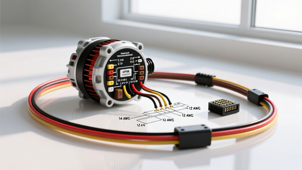
Introduction to the R52 Charging Architecture
The 2015 Nissan Pathfinder, built on the R52 chassis and equipped with the ubiquitous 3.5L VQ35DE V6 engine, utilizes a sophisticated Smart Charge system. Unlike older vehicles where the alternator's internal voltage regulator operated autonomously, the 2015 Pathfinder relies on a continuous handshake between the Engine Control Module (ECM), the Intelligent Power Distribution Module (IPDM), and the 150-amp Denso alternator. Understanding the 2015 Nissan Pathfinder alternator wiring diagram is critical for accurately diagnosing parasitic draws, overcharging conditions, and premature battery failures. This comprehensive walkthrough dissects the high-current output circuits, the low-current PWM communication lines, and the specific OEM wire color codes required for precision troubleshooting.
High-Current B+ Circuit Walkthrough
The high-current side of the charging system is responsible for delivering the bulk amperage generated by the alternator's stator to the vehicle's electrical network and the 12V lead-acid battery. The main output terminal, labeled B+, is secured to the rear of the alternator housing via a 10mm stud and nut.
Cable Routing and AWG Specifications
From the B+ terminal, a heavy-duty 2 AWG stranded copper cable routes upward toward the IPDM located in the engine bay fuse block. This specific gauge is mandated by SAE International standards to handle continuous loads up to 150 amps without exceeding a 0.2-volt drop or generating excessive thermal resistance. The B+ cable terminates at a 150A main fusible link integrated directly into the IPDM bus bar. From the IPDM, a secondary 2 AWG cable routes to the positive battery terminal. Any corrosion at the IPDM bus bar connection point will introduce resistance, causing the alternator to overwork and eventually fail due to thermal saturation.
Low-Current Regulator & Smart Charge Circuit
The low-current side of the 2015 Nissan Pathfinder alternator wiring diagram governs the voltage regulation and ECM telemetry. The alternator features a 2-pin Denso-style regulator connector that facilitates the Smart Charge logic. The ECM monitors electrical load (via IPDM current sensors) and battery temperature to dynamically adjust the alternator's field current, optimizing fuel economy by reducing parasitic drag on the serpentine belt when full charging output is unnecessary.
The Sense (S) and Field Rate (FR) Terminals
The 2-pin connector houses two critical circuits:
- Terminal 1 (S - Sense): This circuit bypasses the IPDM and reads voltage directly at the battery positive post or the main IPDM feed. It ensures the regulator compensates for voltage drop across the main B+ cables.
- Terminal 2 (FR/L - Field Rate / Lamp): This is a Pulse Width Modulated (PWM) communication line. The alternator sends a duty-cycle signal to the ECM indicating its current generation capacity, while the ECM can send a control signal to command higher or lower output based on HVAC load, headlamp status, and engine RPM.
OEM Wire Color Codes and Pinout Reference
When probing the alternator harness connector, referencing the correct OEM wire colors is essential to avoid shorting the 5V ECM reference voltage to the 12V B+ circuit. The table below details the exact pinout for the 2015 Pathfinder 3.5L VQ35DE alternator harness.
| Terminal ID | Pin Number | Circuit Function | OEM Wire Color | AWG Size | Destination / Source |
|---|---|---|---|---|---|
| B+ | N/A (Stud) | Main DC Output | Black w/ Red Stripe (or Bare) | 2 AWG | IPDM Fusible Link / Battery (+) |
| S | Pin 1 | Battery Voltage Sense | Red (R) | 18 AWG | IPDM / Battery Positive Feed |
| FR / L | Pin 2 | Field Rate / ECM Control | Yellow (Y) or Green (G) | 18 AWG | ECM (Pin 42 on ECM Harness) |
| Case | N/A | Chassis / Engine Ground | N/A (Metal-to-Metal) | N/A | Engine Block via Mounting Brackets |
Advanced Diagnostic Procedures
Relying solely on a multimeter to read battery voltage is insufficient for diagnosing modern Smart Charge systems. Follow these advanced diagnostic steps utilizing the 2015 Nissan Pathfinder alternator wiring diagram to isolate faults.
1. B+ and Sense Wire Voltage Drop Test
A common failure mode is a false sense voltage, causing the alternator to push 15.5+ volts, boiling the battery. Set your digital multimeter (DMM) to DC Volts.
Step A: Place the positive probe on the alternator B+ stud and the negative probe on the battery positive post. Start the engine and turn on the headlights and rear defroster to induce a 60+ amp load. The voltage drop must not exceed 0.2V.
Step B: Probe the Pin 1 (Sense) wire at the alternator connector (back-probe using a T-pin) and compare it to the battery positive post. A drop greater than 0.1V on this 18 AWG Red wire indicates high resistance, usually due to a corroded IPDM splice or a failing fusible link housing.
2. Oscilloscope PWM Signal Analysis
To verify the health of the Pin 2 (FR) Yellow wire, an oscilloscope is required. Connect the scope probe to Pin 2 and the ground to the engine block. With the engine running, you should observe a 12V square wave PWM signal. A healthy Denso alternator will typically display a duty cycle between 20% (low charge/minimal electrical load) and 85% (maximum charge/high electrical load). If the signal is a flat 12V or 0V, the internal voltage regulator has failed, or the ECM has lost communication via the IPDM.
Real-World Failure Modes: IPDM and Ground Straps
When diagnosing the 2015 Pathfinder charging system, automotive electrical experts frequently encounter two specific pathologies that mimic a failed alternator.
The IPDM Water Intrusion Flaw
The IPDM on the 2013-2015 Pathfinder is notoriously susceptible to water intrusion from the cowl drain area. When moisture breaches the IPDM seal, it corrodes the internal bus bar where the alternator B+ and Sense circuits interface. This corrosion introduces resistance. The alternator's Sense terminal reads a lower voltage than what is actually at the battery, causing the regulator to overcompensate. Symptoms include the battery venting acid, a illuminated battery warning light, and erratic CVT transmission shifting (as the ECM derates the transmission when it detects voltage anomalies).
Engine-to-Chassis Ground Strap Degradation
The alternator grounds through its aluminum casing to the cast-iron engine block, and subsequently to the chassis via the main 1/0 AWG braided ground strap located near the passenger side engine mount. If this strap corrodes or snaps, the alternator's return current seeks alternative paths, often backfeeding through the throttle body heater circuit or the ECM shielding. Always perform a voltage drop test from the alternator casing to the battery negative terminal; any reading above 0.05V under load dictates immediate cleaning or replacement of the engine ground straps.
Bench Testing and Bypass Procedures
If you have removed the 150A Denso alternator and need to verify its mechanical viability on a bench or in the vehicle without the ECM/IPDM network, you can bypass the Smart Charge system. Warning: This should only be done for brief testing periods, as it forces the alternator to its maximum internal set-point (usually 14.4V).
- Disconnect the 2-pin OEM harness connector from the alternator.
- Connect a jumper wire from the alternator B+ stud directly to Pin 1 (Sense) on the alternator's exposed male terminals.
- Start the engine. By feeding full B+ voltage directly to the Sense terminal and leaving Pin 2 (FR) open, the internal regulator defaults to its base mechanical setting.
- Measure the output at the battery. If the voltage immediately jumps to 14.2V - 14.6V and holds steady under load, the alternator's internal diodes, stator, and regulator are functional, confirming the fault lies within the Nissan IPDM or ECM wiring.
Installation and Torque Specifications
Improper torque on the alternator mounting hardware leads to misalignment, premature serpentine belt wear, and harmonic whining noises. Adhere strictly to Nissan factory torque specifications when reinstalling the unit:
- B+ Terminal Nut (10mm): 12 Nm (106 in-lbs). Overtightening will strip the copper stud from the internal rectifier bridge.
- Alternator Lower Pivot Bolt (17mm): 45 Nm (33 ft-lbs).
- Alternator Upper Adjustment Bracket Bolt (14mm): 25 Nm (18 ft-lbs).
- Serpentine Belt Tensioner Pulley: 38 Nm (28 ft-lbs).
For authoritative wiring schematics and factory service bulletins regarding the VQ35DE charging system, technicians should consult the Nissan North America TechInfo portal or reference the Denso Auto Parts Technical Library for internal regulator component-level diagnostics.