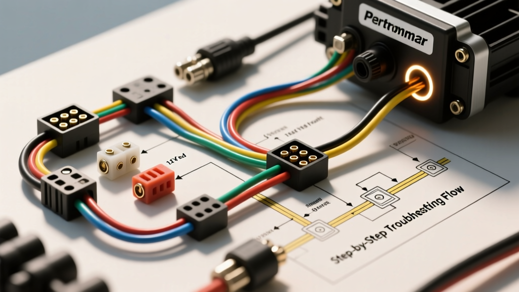
Understanding the Pertronix Ignitor Wiring Diagram
Upgrading from a mechanical breaker-point distributor to a solid-state electronic ignition is one of the most reliable modifications for classic V8 engines. The Pertronix Ignitor series (I, II, and III) utilizes a Hall-effect or magnetic pickup sensor paired with a switching module to eliminate point bounce, arcing, and dwell variation. However, the most common cause of a "cranks-but-no-start" condition after installation is an incorrect interpretation of the Pertronix ignition wiring diagram, specifically regarding the 12-volt switched power feed.
Unlike traditional points systems that require a ballast resistor or OEM resistance wire to drop the voltage to roughly 7-9 volts during normal running (to prevent burning the points), Pertronix modules require a full, unswitched 12V+ supply. Feeding the module through an OEM resistance wire (often a pink cloth-covered wire on classic GM vehicles or a ceramic resistor block on Mopar applications) will result in weak spark, module overheating, and eventual failure.
Module Variations and Wire Functions
- Ignitor I & II (2-Wire Setup): Features a Red wire (12V switched power) and a Black wire (coil negative trigger/ground path). Both are typically 18 AWG stranded copper.
- Ignitor III (3-Wire Setup): Adds a Green wire for the tachometer signal output and integrated multi-spark/rev-limiter functions. The Red and Black wires retain their standard power and ground-trigger roles.
The 12V Relay Bypass: Wiring for Success
To guarantee a clean 12V supply to the Pertronix Red wire and the ignition coil positive terminal, automotive electrical best practices dictate using a standard Bosch-style 12V relay. This prevents voltage drop across the factory ignition switch and bulkhead connector.
Relay Pinout Wiring Flow
| Relay Pin | Function | Wire Gauge | Connection Point |
|---|---|---|---|
| Pin 30 | Constant 12V Battery Power | 10 AWG | Battery Positive (via 15A inline fuse) |
| Pin 87 | Switched 12V Output | 12 AWG | Coil Positive (+) AND Pertronix Red Wire |
| Pin 86 | Relay Trigger (Switched 12V) | 16 AWG | Factory Ignition Switch IGN Terminal |
| Pin 85 | Relay Ground | 16 AWG | Clean Chassis Ground or Engine Block |
By wiring the relay this way, the factory IGN circuit only powers the low-amperage relay coil (Pin 86), while the heavy current required by the ignition coil and Pertronix module is drawn directly from the battery via Pin 30 and 87. For a deeper dive into classic GM ignition switch routing, refer to the Mad Electrical Ignition Tech Guide.
Step-by-Step No-Spark Troubleshooting Flow
If your engine cranks but fails to produce a spark at the plugs, follow this sequential diagnostic flow using a Digital Multimeter (DMM). Never skip steps, as misdiagnosing a bad coil when the issue is a poor ground will lead to unnecessary parts replacement.
Step 1: Verify Switched 12V Power at the Module
- Set your DMM to DC Volts.
- Connect the black probe to a known good engine block ground.
- Back-probe the Pertronix Red wire at the module connector or coil positive terminal with the red probe.
- Have an assistant crank the engine. Specification: You must read a minimum of 10.5V during cranking. If voltage is below 10V, you are still routing through a factory ballast resistor or suffering from severe voltage drop in the ignition switch. Install the relay bypass described above.
Step 2: Test the Ignition Coil Primary and Secondary Circuits
Pertronix modules are highly sensitive to coil resistance. Using a high-resistance "points-style" coil will cause the module to overheat and fail.
- Disconnect the coil wires. Set the DMM to Ohms (Low Range).
- Measure across the small Coil Positive (+) and Coil Negative (-) terminals (Primary Resistance). Specification: Electronic ignition systems require a low-ohm coil, typically between 0.5 and 1.5 ohms. If your coil reads 3.0+ ohms, replace it with an E-Core or specific electronic ignition coil.
- Measure from the Coil Negative (-) terminal to the center high-tension tower (Secondary Resistance). Specification: Should read between 8,000 and 12,000 ohms (8k-12k). An open circuit (OL) indicates a broken internal secondary winding.
Step 3: Inspect the Ignitor Module Ground and Air Gap
The Pertronix module switches the coil by completing the ground path through the Black wire. If the module lacks a proper internal ground reference or the magnetic air gap is incorrect, the Hall-effect sensor will not trigger.
- Remove the distributor cap and rotor.
- Inspect the Black wire terminal at the coil negative. Ensure it is not sharing a terminal with a condenser (capacitor). Crucial: You must completely remove the factory points condenser; leaving it in the circuit will short the Pertronix signal to ground.
- Check the air gap between the module sensor and the magnetic reluctor ring. Use a brass or plastic feeler gauge. Never use a steel feeler gauge, as the steel will attract the Alnico magnets and alter the gap or scratch the ring. Specification: The gap must be set between 0.030" and 0.050".
Pertronix Ignitor Wiring Specification Chart
| Wire Color | AWG Size | Function | Connection / Routing Notes |
|---|---|---|---|
| Red | 18 AWG | 12V Switched Power | Must be full battery voltage (12V+). Do not route through OEM ballast resistor. |
| Black | 18 AWG | Coil Trigger / Ground Path | Connects exclusively to Coil Negative (-). Remove factory condenser. |
| Green (Ignitor III) | 18 AWG | Tachometer / Rev Limiter | Connects to tachometer signal input. Do not connect to 12V source. |
Common Failure Modes & Real-World Fixes
Failure Mode 1: Leaving the Key in the "ON" Position
Symptom: Module works perfectly for a few weeks, then suddenly dies with zero spark.
Cause: Unlike points, the Pertronix Ignitor I and II modules do not have a built-in dwell limiter (unless using Ignitor II with adaptive dwell). If the ignition key is left in the "ON" position without the engine running, the module will continuously ground the coil, drawing 4 to 8 amps constantly. This will melt the internal switching transistor and destroy the module in under 15 minutes.
Fix: Always turn the key off if the engine is not running. If you frequently work on the car with the key on for radio/accessory power, wire a secondary toggle switch to interrupt the 12V feed to the coil and module.
Failure Mode 2: Incorrect Reluctor Ring Polarity
Symptom: Engine backfires through the carburetor or timing is impossible to set.
Cause: Pertronix manufactures specific kits for male and female cap distributors (e.g., GM HEI vs. standard Delco, or Ford Duraspark). The magnetic polarity of the reluctor ring is matched to the Hall-effect sensor. Installing a ring designed for a female cap distributor into a male cap distributor will result in the spark firing at the exact wrong moment in the rotation cycle.
Fix: Verify the exact Pertronix part number against your distributor casting number. Refer to the Pertronix Official Installation Guides to ensure the correct magnet sleeve orientation.
Failure Mode 3: Tachometer Interference
Symptom: Engine runs rough at high RPM, or the tachometer needle bounces erratically.
Cause: On older vehicles, analog tachometers were wired in series with the coil negative terminal. The Pertronix module's rapid switching creates high-frequency voltage spikes that confuse older tachometer circuitry, which in turn can feed "noise" back into the Black trigger wire.
Fix: Install a tachometer filter (capacitor) between the tach signal wire and ground, or upgrade to an Ignitor III which utilizes the dedicated Green wire to provide a clean, isolated square-wave tachometer signal.