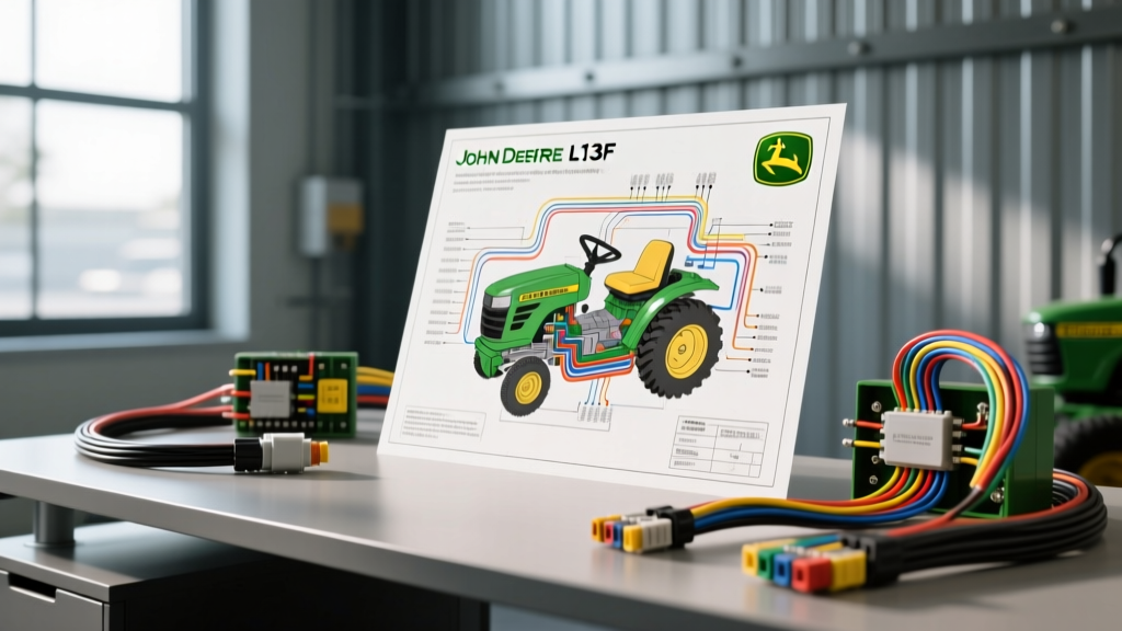
The Danger of Generic John Deere L130 Wiring Diagram PDFs
When troubleshooting a no-start condition, a dead battery, or a PTO clutch failure on a 23-HP John Deere L130 lawn tractor, the first instinct is to search for a John Deere L130 wiring diagram PDF. However, relying on generic or mislabeled schematics found on third-party forums is one of the most common causes of severe electrical damage in the L100 series. While the L110, L120, L130, and L140 share a similar chassis footprint, their wiring harnesses differ significantly based on the engine manufacturer (Kawasaki vs. Kohler), the charging system stator output, and the PTO engagement mechanism (manual lever vs. electric Warner-style clutch).
Applying an L110 schematic to an L130 with an electric PTO will result in immediate harness overheating, as the base models lack the dedicated 14 AWG PTO feed circuits and reverse-bias diode protection. This guide outlines the critical safety warnings and the top five wiring mistakes technicians and DIYers make when interpreting L130 schematics.
Critical Safety Warnings Before Probing the Harness
Before you connect a multimeter or begin splicing wires based on your downloaded PDF, you must adhere to strict automotive electrical safety protocols. The L130 operates on a 12V DC negative-ground system, but the starter motor can draw in excess of 150 amps under load, and the Kawasaki V-Twin stator generates dangerous AC voltages.
- Battery Disconnect Protocol: Always disconnect the negative (-) battery terminal first and isolate it. The main battery feed wire (typically 8 AWG or 10 AWG Red) runs directly from the battery positive terminal to the starter solenoid and is completely unfused. Accidentally grounding this wire with a probe or wrench will instantly weld metal and cause a harness fire.
- PTO Capacitor Discharge: If your L130 is equipped with an electric PTO clutch, the circuit includes a suppression capacitor or diode to prevent voltage spikes. Disconnecting the battery does not instantly drain this component. Shorting the PTO connector pins with a screwdriver can result in a severe spark and damage to the interlock module.
- Multimeter Fusing Errors: Never test the starter solenoid trigger wire or the main battery feed using the multimeter's 10A current port in parallel. This will create a dead short across the battery. Always test for Voltage (VDC) or Resistance (Ohms) with the leads in the correct COM and V/Ohms ports.
The Top 5 Wiring Mistakes L130 Owners Make
1. Bypassing the Safety Interlock Logic System
The most frequent and dangerous mistake is attempting to bypass the John Deere safety interlock system to troubleshoot a stalling issue. The L130 utilizes a complex logic circuit involving the seat switch (Normally Closed), the brake pedal switch, and the PTO engagement switch. If the operator leaves the seat while the PTO is engaged, the interlock module grounds the ignition magneto, killing the engine.
DIYers often misinterpret the wiring diagram and jump the seat switch pins with a paperclip or splice the wires together. Because the seat switch is Normally Closed (circuit completes when the seat is empty), bypassing it incorrectly will either cause the tractor to stall immediately upon sitting down or, far worse, defeat the safety mechanism entirely, allowing the mower blades to remain engaged if the operator falls off the machine. Always test the switches for continuity using a multimeter rather than bypassing them.
2. Misidentifying the Ignition Switch Terminals
The L130 uses a 5-pin or 6-pin ignition switch depending on the exact production run and lighting package. Confusing the 'S' (Start) and 'M' (Magneto) terminals is a classic error that results in frying the ignition switch contacts or failing to kill the engine.
| Terminal Letter | Function | OEM Wire Color | AWG Size | Testing Notes |
|---|---|---|---|---|
| B | Battery (12V+ Input) | Red | 12-14 AWG | Constant 12V+ relative to chassis ground. |
| L | Lights / Accessory | Yellow / White | 16 AWG | 12V+ output only in 'Run' and 'Start' positions. |
| A | Accessory (PTO Feed) | White | 14 AWG | Powers the PTO clutch relay coil in 'Run'. |
| S | Starter Solenoid Trigger | Purple | 14-16 AWG | 12V+ output ONLY in the 'Start' crank position. |
| M | Magneto Kill (Ground) | Black | 16 AWG | Grounds ignition coils in 'Off' position to kill spark. |
3. Undersizing the Starter Solenoid Feed Wire
When replacing a corroded starter solenoid or repairing a damaged main harness, many DIYers use whatever wire they have on hand. The trigger wire from the ignition switch 'S' terminal to the solenoid can be 16 AWG, but the main battery feed and the output to the starter motor must be a minimum of 8 AWG or 10 AWG stranded copper, as outlined in the SAE J1128 Standard for Low Tension Primary Cable. Using 14 AWG wire for the main starter feed will cause massive voltage drop under the 150A cranking load, leading to melted insulation, solenoid welding, and a no-crank condition.
4. Ignoring the Voltage Regulator Ground Path
The Kawasaki V-Twin engine on the L130 uses a stator that outputs roughly 28 to 35 Volts AC at high RPM. The external voltage regulator/rectifier converts this to 13.8V - 14.4V DC to charge the battery. A very common mistake when reading the wiring diagram is assuming the regulator only relies on its wire harness. In reality, the regulator body must be grounded to the engine block via its mounting bolts. If you replace the regulator and fail to clean the mounting surface down to bare metal, the internal rectifier bridge will overheat and fail within hours, leaving you with a dead battery.
5. PTO Clutch Connector & Diode Failures
The electric PTO clutch on the L130 typically draws between 2.5 and 3.0 Amps at 12V DC. The resistance across the clutch coil should measure between 3.5 and 4.5 Ohms. A major mistake occurs when replacing the PTO clutch harness connector and ignoring the inline reverse-bias diode. This diode is critical; it absorbs the inductive voltage spike (which can exceed 100V) generated the moment the PTO switch is turned off. If you wire the replacement harness backward or omit the diode, the voltage spike will arc across the ignition switch contacts or blow the internal traces of the safety interlock module. Always consult the Warner Electric PTO Clutch Installation Guidelines for proper diode orientation (stripe facing the 12V+ source).
Proper Wire Gauge & Crimp Specifications
When repairing a harness based on your John Deere L130 wiring diagram PDF, soldering is generally discouraged in high-vibration agricultural environments due to solder wicking and wire embrittlement. Instead, use adhesive-lined heat shrink crimp terminals.
| Application | Required AWG | Terminal Type | Max Ampacity (SAE J1128) |
|---|---|---|---|
| Battery to Solenoid / Starter | 8 AWG or 10 AWG | Ring Terminal (5/16' stud) | 150A+ (Cranking surge) |
| Main Harness 12V Feed | 12 AWG | Butt Splice / Heat Shrink | 41 Amps |
| PTO Clutch Feed | 14 AWG | Weather-Pack Pin (Male/Female) | 32 Amps |
| Ignition / Interlock Logic | 16 AWG to 18 AWG | Spade / Weather-Pack | 24 Amps |
Authoritative References & OEM Resources
To ensure you are working with the correct schematic for your specific serial number break, always cross-reference your findings with official documentation. Generic PDFs cannot account for mid-year production harness revisions. For exact part numbers and harness routing, utilize the John Deere Parts & Maintenance Documentation portal using your tractor's 13-character PIN. Furthermore, adhering to SAE J1128 standards for wire insulation and ampacity will ensure your repairs survive the harsh, high-vibration, and high-heat environment of the L130 engine bay.