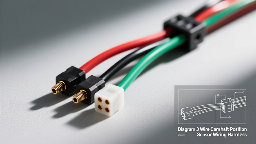
Understanding the 3-Wire Camshaft Position Sensor Harness
The 3-wire camshaft position (CMP) sensor is a critical engine management component, typically utilizing a Hall-effect design to provide the Powertrain Control Module (PCM) with precise camshaft timing data. Unlike 2-wire variable reluctance sensors, a 3-wire Hall-effect CMP requires a dedicated power supply, a clean ground, and a signal return circuit. Because these sensors are mounted directly on the engine block or timing cover, the wiring harness is subjected to extreme thermal cycling, high-frequency engine vibrations, and exposure to hydrocarbons. Over time, insulation chafing, terminal fretting corrosion, and oil intrusion via capillary action lead to intermittent P0340 or P0341 diagnostic trouble codes. Understanding the diagram 3 wire camshaft position sensor wiring harness layout is the first step in executing a permanent, professional-grade repair rather than relying on temporary electrical tape fixes.
The Diagram: 3 Wire Camshaft Position Sensor Wiring Harness Pinout
While specific wire colors vary by manufacturer, the fundamental architecture of a 3-wire Hall-effect CMP sensor remains consistent across most modern OBD-II vehicles. Below is a representative pinout and wiring diagram specification based on the widely serviced General Motors LS-series and GM Gen V LT engine platforms, which utilize the Delphi Metri-Pack 280 connector system.
| Connector Pin | Circuit Function | OEM Wire Color (GM Example) | Wire Gauge (AWG) | PCM Cavity Reference |
|---|---|---|---|---|
| Pin A | Sensor Ground | Black / White Stripe | 20 AWG | PCM X2, Pin 4 |
| Pin B | CMP Signal Output | Yellow | 20 AWG | PCM X1, Pin 22 |
| Pin C | 12V Reference / Ignition | Pink | 18 AWG | Fuse Block / PCM X2 |
Note: Always verify the specific diagram 3 wire camshaft position sensor wiring harness schematic for your exact make, model, and year using factory service information, as PCM pinouts and reference voltages (some systems use a 5V reference instead of 12V) will vary.
Cost Analysis: Harness Replacement Strategies
When the factory harness degrades, technicians and DIYers face three primary repair paths. The cost and longevity of each approach vary significantly based on the materials and tools utilized.
1. Dealership OEM Complete Harness Replacement
Purchasing a complete engine wiring harness from an OEM dealership is the most foolproof but expensive method. For a GM LS or Ford Coyote engine, a complete front dress harness can cost between $250 and $600. This requires removing the intake manifold, alternator, and various accessories to route the new loom. Verdict: Cost-prohibitive for a single sensor circuit failure.
2. OEM Pigtail Repair Kit
Most auto parts stores sell pre-wired pigtails (typically 6 to 12 inches long) with the correct molded connector. These cost between $15 and $35. While convenient, the wire used in cheap aftermarket pigtails is often standard PVC (not automotive-grade TXL), and the included butt-connectors are prone to failure if not crimped and sealed correctly. Verdict: Moderate cost, moderate reliability.
3. Custom Loom Fabrication (Professional Method)
Building a custom repair harness using bulk automotive wire, OEM terminals, and proper sealing costs roughly $25 to $40 in materials but yields a harness that exceeds factory specifications in durability. Verdict: Lowest long-term cost, highest reliability.
| Repair Method | Estimated Material Cost | Labor Time | Longevity Rating |
|---|---|---|---|
| OEM Full Harness | $250 - $600+ | 3.0 - 5.0 Hours | 10+ Years |
| Aftermarket Pigtail | $15 - $35 | 0.5 - 1.0 Hour | 1 - 3 Years |
| Custom Fabricated Loom | $25 - $40 | 1.0 - 1.5 Hours | 10+ Years |
Tool Requirements for Professional Harness Repair
To execute a custom harness repair that matches OEM standards, specific automotive electrical tools are mandatory. Standard household crimpers and hardware store wire will result in voltage drops and premature failure.
- Wire Strippers: Precision micro-strippers calibrated for 18-22 AWG. Standard heavy-duty strippers will nick the copper strands, reducing the current-carrying capacity and creating a fatigue point.
- Ratcheting Terminal Crimper: A crimper specifically calibrated for the terminal family in use. For GM applications, a Delphi Metri-Pack 280 crimper (such as the Pico 07042 or equivalent) is required to achieve the correct F-crimp geometry on the wire barrel and B-crimp on the insulation grip.
- Terminal Extraction Tools: Metri-Pack 280 and Weather-Pack extractors are necessary to remove damaged terminals from the plastic connector shroud without breaking the locking tangs.
- Heat Gun and Dual-Wall Heat Shrink: 3:1 shrink ratio polyolefin tubing with an inner layer of marine-grade adhesive sealant. This prevents moisture and oil from wicking into the wire strands.
- Digital Multimeter (DMM) & Oscilloscope: A DMM is required for continuity and resistance testing, while an automotive oscilloscope (like a PicoScope) is essential for verifying the digital square wave signal integrity under dynamic engine conditions.
Wire Selection: SAE J1128 Standards
Never use standard PVC-insulated wire for under-hood sensor harnesses. According to SAE International J1128 standards, automotive engine bay wiring must utilize cross-linked polyethylene insulation, commonly known as TXL, GXL, or SXL. TXL (Thin-wall Cross-Linked) is the industry standard for modern engine harnesses due to its high-temperature resistance (up to 125°C / 257°F) and excellent abrasion resistance. For the CMP signal and ground circuits, 20 AWG TXL is optimal, providing sufficient conductivity while remaining flexible enough to route through tight engine bays. The 12V reference circuit may utilize 18 AWG TXL to minimize voltage drop over longer harness runs.
Step-by-Step Harness Repair Execution
- Circuit Isolation: Disconnect the negative battery terminal and unplug the PCM connector to prevent accidental shorting of the 12V reference circuit to the signal ground.
- Damage Assessment: Trace the harness back from the CMP sensor connector. Cut the harness a minimum of 6 inches past any visible chafing, heat damage, or oil intrusion to ensure you are splicing into healthy, uncontaminated copper.
- Terminal Depinning: Use the Metri-Pack 280 extraction tool to release the locking tang and pull the damaged terminals out of the plastic connector housing.
- Preparation and Stripping: Cut three lengths of TXL wire (Pink, Yellow, Black/White). Strip exactly 3mm (1/8 inch) of insulation from each end. Do not twist the bare copper strands.
- Precision Crimping: Insert the stripped wire into the Delphi 12191818 female terminal. Use the ratcheting crimper to form the wire barrel crimp. Inspect the crimp; the wire strands should be visible at the front of the barrel, and the insulation grip should securely hold the TXL jacket without cutting into it.
- Sealing and Reassembly: Slide dual-wall adhesive heat shrink over the crimped wire and apply heat until the adhesive purges slightly from the ends. Insert the new terminals into the connector housing until you hear a definitive click.
- Loom Integration: Splice the new pigtail into the main engine harness using sealed butt-splices or ultrasonic welding. Wrap the entire repair section in high-temperature harness tape (e.g., Tesa 51036) and secure it with split-loom tubing and factory-style P-clips.
Post-Repair Validation with an Oscilloscope
Because the diagram 3 wire camshaft position sensor wiring harness carries a high-frequency digital signal, a multimeter is insufficient for final validation. A multimeter will only show an average DC voltage (typically 2.5V to 6V), masking intermittent dropouts caused by poor crimps or high resistance. As detailed in Pico Technology's automotive oscilloscope training library, connecting a scope to the signal wire (Pin B) while cranking the engine will reveal a 0V to 12V (or 0V to 5V) square wave. The waveform should feature perfectly vertical rising and falling edges with zero ringing or voltage sag at the peak. If the signal drops to 2V instead of 0V on the low side, or peaks at 9V instead of 12V, you have a high-resistance fault in the ground or power circuit, respectively, necessitating a re-evaluation of your crimps and splice points.
Summary
Repairing a 3-wire CMP sensor harness requires more than just matching wire colors. By understanding the underlying Hall-effect circuit diagram, investing in SAE-compliant TXL wire, utilizing Metri-Pack specific crimping tools, and validating the square wave signal with an oscilloscope, you can execute a permanent repair that restores factory-level engine management reliability at a fraction of the OEM harness replacement cost.