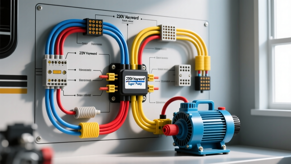
Integrating High-Draw 230V Accessories into Vehicle Power Systems
Mobile detailing rigs, off-grid luxury RVs, and custom overland watercraft trailers frequently require high-volume fluid transfer. While standard 12V DC diaphragm pumps are common for low-demand applications, heavy-duty mobile setups demand the reliability and high gallons-per-minute (GPM) output of AC induction motors. When technicians search for a 230 volt Hayward Super Pump wiring diagram 230v configuration for mobile applications, they are usually trying to solve the complex challenge of bridging residential AC induction motors with automotive DC power architectures.
The Hayward Super Pump (frequently equipped with Century or A.O. Smith 1HP to 2HP motors) is a staple for high-volume water transfer from belly tanks to pressurized buffer tanks in mobile units. However, wiring this 230V AC equipment into a vehicle requires strict adherence to mobile electrical codes, precise inverter sizing, and proper terminal board configuration. This beginner-friendly guide breaks down the fundamentals of safely wiring a 230V Hayward pump to a mobile 24V DC battery bank and pure sine wave inverter system.
Understanding the Load Profile and Inverter Sizing
Before cutting any wire, you must understand the electrical demands of the pump motor. A standard 1HP Hayward Super Pump motor operating at 230V draws approximately 7.4 to 8.0 Full Load Amps (FLA). However, AC induction motors experience a massive current draw during startup, known as Locked Rotor Amps (LRA). The LRA for these motors can spike to 45 Amps or more for a fraction of a second.
If you are powering this from a vehicle's auxiliary battery bank via an inverter, the inverter must handle the continuous wattage (roughly 1,800W to 2,000W accounting for motor efficiency and power factor) and the surge wattage (upwards of 10,000W peak). Therefore, a minimum 3000W continuous / 6000W surge Pure Sine Wave inverter is mandatory. Using a Modified Sine Wave (MSW) inverter will cause the AC motor to overheat rapidly, degrade the insulation on the stator windings, and trip the motor's internal thermal overload protector within minutes.
DC Side: Battery Bank to Inverter Wiring
The foundation of any high-draw vehicle accessory is the DC wiring. A 3000W inverter pulling from a 24V DC battery bank will draw roughly 125 Amps continuously, and significantly more during the pump's startup surge. Undersized DC cables will result in severe voltage drop, causing the inverter's Low Voltage Disconnect (LVD) to trigger and shut down the system mid-cycle.
- Wire Gauge: Use 2/0 AWG SGX (Standard Gauge for Battery Cable) or 2/0 AWG THHN copper wire for runs up to 10 feet. For runs exceeding 10 feet, step up to 4/0 AWG to maintain a voltage drop below 3%.
- Overcurrent Protection: Install a 250A ANL or Class T fuse on the positive DC cable, located within 18 inches of the battery bank positive terminal, as mandated by NFPA 1192 RV Electrical Standards.
- Termination: Use heavy-duty copper lugs with a closed-end barrel. Crimp using a 6-ton hydraulic crimper, and apply a heat-shrink seal. Torque the inverter DC busbar nuts to the manufacturer's specification (typically 12 Nm to 15 Nm for M8 studs).
AC Side: Inverter to Pump Motor Wiring
Once the DC side is secured, the AC output from the inverter must be routed to the pump. In a mobile environment, vibration and moisture are the primary enemies of AC wiring.
Conduit and Wire Selection
For the 230V AC run, use 10 AWG THHN/THWN-2 stranded copper wire. This gauge is rated for 30 Amps, which comfortably exceeds the pump's FLA and provides a safety margin for voltage drop over longer conduit runs inside a trailer or RV chassis. The wires must be routed through Liquid-Tite Flexible Metallic Conduit (LFMC) to protect against abrasion, road debris, and moisture ingress.
For 230V split-phase wiring, the standard mobile color code is:
- Line 1 (L1): Black
- Line 2 (L2): Red (or Blue)
- Ground (GND): Green or Bare Copper
Install a 2-pole 15 Amp or 20 Amp AC breaker in a DIN-rail mounted distribution panel between the inverter and the pump. This provides localized overcurrent protection and a convenient disconnect switch for maintenance.
The 230 Volt Hayward Super Pump Wiring Diagram 230v: Terminal Board Configuration
The most critical step in the installation is configuring the motor's internal terminal board. Hayward Super Pumps typically utilize Century (formerly A.O. Smith) single-phase induction motors. These motors are dual-voltage (115V/230V) and must be physically wired for 230V before applying power. Wiring a 230V supply into a motor configured for 115V will instantly destroy the windings and poses a severe fire hazard.
Access the terminal board by removing the rear electrical cover of the motor. You will see a terminal block with numbered pins (typically 1 through 5) and a green grounding screw.
| Terminal Pin | 230V Configuration | Wire Color (Mobile AC) | Function |
|---|---|---|---|
| Pin 1 | Connect L1 | Black | AC Line 1 (Hot) |
| Pin 2 | Isolated / Jumper | N/A | Internal Start Winding (Do not connect external power) |
| Pin 3 | Isolated / Jumper | N/A | Internal Centrifugal Switch (Do not connect external power) |
| Pin 4 | Isolated / Jumper | N/A | Internal Run Winding (Do not connect external power) |
| Pin 5 | Connect L2 | Red | AC Line 2 (Hot) |
| Green Screw | Connect Ground | Green | Equipment Grounding Conductor (EGC) |
Note: Always verify the specific wiring diagram printed on the inside of the motor's electrical cover, as terminal layouts can vary slightly between manufacturing years. Refer to the Hayward Super Pump Installation Manual for model-specific schematics.
Vibration Mitigation for Terminal Connections
Vehicle chassis vibration can loosen terminal screws over time, leading to high-resistance connections, arcing, and melted terminal blocks. To prevent this:
- Apply a small amount of anti-oxidant paste (e.g., Noalox) to the stripped copper wire ends before insertion to prevent corrosion in humid mobile environments.
- Use a calibrated torque screwdriver to tighten the terminal screws to approximately 1.2 Nm to 1.5 Nm.
- Apply a drop of blue threadlocker (Loctite 242) to the threads of the terminal screws if the motor manufacturer permits, or use star-lock washers to maintain tension.
Grounding and Bonding in a Mobile Chassis
Grounding a 230V AC motor in a vehicle is fundamentally different from grounding it in a residential home. In a house, the ground rod and utility neutral provide the earth reference. In an RV or mobile truck, the vehicle chassis acts as the ground plane.
The Equipment Grounding Conductor (the green wire) from the pump motor must travel all the way back to the AC distribution panel's ground busbar, which is bonded to the inverter's chassis ground. The inverter's chassis ground must then be bonded to the vehicle's steel frame using a minimum 6 AWG copper wire. Do not rely on the pump's mounting bolts to the vehicle frame for the AC ground path; the rubber vibration isolation mounts used to dampen pump noise will break the electrical continuity, creating a lethal shock hazard if a winding shorts to the motor casing. Adhering to SAE J1113 EMC and safety guidelines ensures that fault currents have a low-impedance path back to the inverter to trip the breaker instantly.
Troubleshooting Common Mobile Pump Failures
Even with perfect wiring, mobile environments introduce unique failure modes. Use this diagnostic tree if the pump fails to operate correctly:
Symptom: Motor Hums but Does Not Spin
- Cause 1: Incorrect terminal board configuration. If wired for 115V but supplied with 230V, the thermal overload will trip immediately. If wired for 230V but supplied with 115V (due to a misconfigured inverter), the motor lacks the torque to start.
- Cause 2: Failed start capacitor. The vibration of off-road travel can fracture the internal foil of the start capacitor located under the rear motor hump.
Symptom: Inverter Shuts Down with 'Low Battery' Fault
- Cause: Excessive DC voltage drop. The inverter is seeing a voltage sag below its 21V cutoff threshold during the pump's LRA surge. Check for loose crimps on the 2/0 AWG battery cables, corroded busbars, or an undersized battery bank that cannot deliver the required 150A+ instantaneous DC current.
Symptom: Motor Overheats and Trips After 10 Minutes
- Cause: Modified Sine Wave (MSW) inverter usage. MSW power creates harmonic distortion that generates excess heat in the stator windings of AC induction motors. You must upgrade to a Pure Sine Wave inverter to ensure clean 60Hz power that matches utility grid quality.
By treating the 230V Hayward Super Pump not just as a plumbing component, but as a high-draw electrical load integrated into a dynamic automotive power system, you ensure reliable, safe, and long-lasting operation for any mobile fluid transfer application.