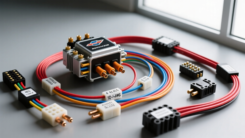
Introduction to Chevy 350 HEI Ignition Systems
Swapping a traditional points-style ignition to a High Energy Ignition (HEI) system on a classic Chevy 350 Small Block (SBC) remains one of the most reliable and effective performance upgrades available. Introduced by General Motors in 1974, the HEI system consolidates the ignition coil and electronic control module directly into the distributor cap, eliminating the external ballast resistor and condenser. However, executing this swap requires a precise understanding of the HEI distributor wiring diagram Chevy 350 configurations, particularly when navigating the differences between OEM Delco-Remy units and modern aftermarket alternatives like MSD, Summit Racing, and Davis Unified Ignition (DUI).
Unlike older points systems that operated on a reduced 9V circuit, the HEI system demands a full, unswitched 12 volts at wide-open throttle to saturate the high-output coil. Failing to provide adequate voltage and current capacity is the leading cause of weak spark, misfires, and premature module failure in SBC 350 builds. This guide breaks down the exact wiring schematics, product comparisons, and relay bypass strategies required to properly power your Chevy 350 HEI distributor.
Core 4-Pin HEI Distributor Wiring Diagram & Pinout
The foundation of the Chevy 350 HEI system is the 4-pin ignition control module. Whether you are using a factory GM cap with the integrated coil or an aftermarket unit, the primary cap terminals and module pins remain largely consistent. According to SAE J1128 Low Tension Cable Standards, selecting the correct wire gauge is critical to prevent voltage drop across the harness.
| Cap Terminal | Module Pin | Wire Color (OEM) | Function | Required AWG |
|---|---|---|---|---|
| BAT | N/A | Pink (OEM) / Red (Aftermarket) | Switched 12V Power Feed | 12 AWG |
| TACH | N/A | Orange / White | Tachometer Signal Output | 14 AWG |
| N/A | G (Ground) | Black / White | Module to Distributor Base Ground | 16 AWG |
| N/A | C (Coil) | White | Coil Negative Trigger | 16 AWG |
Expert Note: The 'G' pin on the module grounds through the distributor base to the engine block. On older Chevy 350s with oxidized aluminum intake manifolds or painted engine blocks, this ground path can become compromised. Always run a dedicated 16 AWG ground wire from the distributor base hold-down bolt to a clean, bare metal point on the cylinder head or engine block.
The Chevy 350 'Pink Wire' Voltage Drop Problem
The most common wiring mistake when installing an HEI distributor on a pre-1974 Chevy 350 is reusing the factory ignition feed wire. Early SBC 350s equipped with points-style ignitions utilized a specialized cloth-covered resistance wire (often pink) designed to drop the system voltage from 12V down to 9V once the engine was running. This protected the points from burning out.
If you connect your new HEI BAT terminal to this factory resistance wire, your distributor will only receive 7 to 9 volts under load. This results in a weak spark, hesitation at high RPMs, and excessive heat buildup inside the HEI module, which will quickly fry the internal switching transistor. To properly wire the HEI, you must bypass the factory resistance wire and run a new, dedicated 12 AWG switched 12V wire from the ignition switch's IGN terminal on the fuse box directly to the BAT spade on the distributor cap.
Product Comparison: Selecting Your HEI Distributor
Not all HEI distributors are wired identically. Aftermarket manufacturers have introduced variations to improve high-RPM spark stability, alter the physical footprint, or integrate with modern EFI systems. Below is a comparison of the most popular Chevy 350 HEI options and their specific wiring requirements.
| Brand / Model | Module Type | Coil Style | Wiring Quirk / Requirement | Best Application |
|---|---|---|---|---|
| GM OEM (Delco-Remy) | 4-Pin | Coil-in-Cap | Requires full 12V bypass; large cap may interfere with tall valve covers. | Daily Driver / Budget Restoration |
| Summit Racing HEI | 4-Pin | Coil-in-Cap | Standard BAT/TACH spades; includes adjustable vacuum advance. | Street Performance / Mild Cams |
| MSD Ready-to-Run | Magnetic Trigger | External Coil | Requires 3-pin Weather-Pack connector; must use MSD external coil and ballast bypass. | High RPM / Racing / Tight Clearances |
| DUI (Davis Unified) | Custom High-Dwell | Coil-in-Cap | Requires 14V alternator output for maximum spark; uses heavier 10 AWG feed. | Off-Road / Heavy Towing / Nitrous |
Understanding Tachometer Wiring Differences
When upgrading from points to HEI, your Chevy 350's analog tachometer wiring must also be updated. Points-style tachometers trigger off the negative side of the external coil. The HEI system provides a dedicated TACH terminal on the cap. This terminal outputs a 12V square wave pulse. If your aftermarket tachometer is not registering RPMs, you may need to install a tachometer filter (a small capacitor) across the TACH terminal and ground to smooth the signal, a common requirement noted in Haynes Chevy Full-Size Service Manuals for early 70s GM sweep-style gauges.
5-Pin and 7-Pin Module Upgrades: Wiring the Differences
While the 4-pin module is the standard for carbureted Chevy 350s, enthusiasts running aggressive camshafts or early computer-controlled engines may encounter 5-pin or 7-pin modules.
- 5-Pin HEI Module: The fifth pin is typically used for a dwell control circuit or a tachometer filter ground. In performance applications, wiring a potentiometer to the 5th pin allows you to manually adjust the ignition coil dwell time, increasing spark duration at high RPMs.
- 7-Pin HEI Module (Computer Controlled): Found in mid-80s Chevy 350s with early ECM integration, the 7-pin module features additional wires (usually Brown and Yellow) that connect to the Engine Control Module. These pins allow the computer to retard timing electronically. If you are retrofitting a 7-pin distributor into a carbureted SBC 350, you must wire the 'B' and 'C' computer pins to a specific ground/12V configuration to lock the timing, otherwise the module will default to a severe base timing retard.
Step-by-Step: The 30A Relay Bypass Wiring Strategy
For high-performance Chevy 350 builds utilizing DUI or high-output aftermarket HEI systems, drawing 7+ amps directly through the factory ignition switch can overheat the switch contacts over time. The safest and most efficient wiring method is to use a standard Bosch-style 30A relay to feed the distributor directly from the battery. MSD Performance Technical Notes highly recommend relay-driven ignition feeds for high-draw systems.
Relay Wiring Diagram Configuration
- Pin 30 (Power In): Run a 10 AWG red wire directly from the positive battery terminal. Install an inline 20A ATO fuse within 6 inches of the battery.
- Pin 85 (Ground): Run a 14 AWG black wire to a clean, unpainted chassis ground near the relay.
- Pin 86 (Trigger): Connect a 16 AWG wire to your dash's switched 12V ignition source. Pro Tip: You can safely use the factory pink resistance wire to trigger Pin 86. The relay coil draws less than 150mA, so the voltage drop across the resistance wire will not affect the relay's ability to engage.
- Pin 87 (Power Out): Run a 12 AWG red wire directly to the BAT spade terminal on the HEI distributor cap.
This setup ensures your Chevy 350 HEI receives maximum voltage with zero resistance, while protecting your vintage ignition switch from high amperage loads.
Common Chevy 350 HEI Wiring Troubleshooting
Even with the correct diagram, real-world engine bay conditions can introduce electrical faults. Use this decision tree to diagnose common HEI issues on the SBC 350.
| Symptom | Probable Cause | Diagnostic Fix |
|---|---|---|
| Engine dies when hot, restarts after cooling | Module thermal failure due to voltage drop | Check voltage at BAT terminal with engine running. Must be >11.5V. Upgrade to relay bypass. |
| Backfiring through carburetor at high RPM | Spark blowout or weak coil saturation | Verify 12 AWG wire is used. Check distributor cap for carbon tracking between coil and rotor. |
| Tachometer needle bouncing erratically | RFI interference or missing tach filter | Ensure spark plug wires are suppressed (carbon core). Install 0.22µF capacitor on TACH terminal. |
| No spark when cranking, spark when key released | Wired to 'Start' instead of 'Run' circuit | Move BAT feed to the IGN (Run) terminal on the fuse block, ensuring it stays hot in both Run and Start. |
Final Torque and Assembly Specifications
Proper wiring is only half the battle; physical installation dictates the grounding and timing stability of the HEI system. When installing the distributor into the Chevy 350 block, ensure the O-ring is lubricated with engine oil to prevent binding. Torque the distributor hold-down bolt to 18-22 lb-ft. Over-torquing can warp the aluminum base, breaking the internal ground path for the module's 'G' pin. Finally, secure the HEI cap using the provided screws, torquing them to 15-20 in-lb to prevent cracking the plastic housing while ensuring a weather-tight seal against the silicone O-ring.