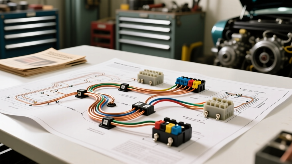
The 1967 Mustang Electrical System: A Watershed Year
The 1967 model year marked a massive evolution for the Ford Mustang. The chassis was widened, the engine bay was enlarged to accommodate the 390 cubic-inch V8, and the electrical system underwent significant revisions. For classic car restorers and mechanics, studying a 1967 Mustang wiring diagram is critical, as this was the first year Ford utilized a fully integrated alternator system alongside an ammeter gauge, replacing the generator and idiot-light setups of earlier years. However, this transitional harness design is fraught with unique failure points. Misinterpreting the 1967 schematics often leads to catastrophic dead shorts, melted under-dash harnesses, and severe fire hazards. Below, we detail the most dangerous wiring mistakes made on the 1967 Mustang and provide actionable, OEM-correct safety protocols.
Critical Mistake #1: The Ammeter Shunt Wiring Confusion
Unlike the warning light harnesses introduced in 1968, the 1967 Mustang features a factory ammeter. This gauge does not measure current directly through the dashboard; instead, it uses a shunt-type setup. The main alternator output wire (10 AWG Black with a Yellow stripe) routes from the starter solenoid, directly behind the dash panel, through a heavy copper shunt, and back out to the main harness.
The Fire Hazard
The most common and dangerous mistake occurs when restorers attempt to adapt a later-model '68 or '69 warning-light dash harness into a '67 chassis, or when they improperly route the 10 AWG Black/Yellow ammeter feed wires. Because these wires carry the full alternator output (up to 55 amps on stock Autolite units), they generate significant heat. If these wires are zip-tied against the sharp metal edges of the dash frame without OEM-style rubber grommets or split-loom shielding, the insulation degrades. A dead short here bypasses the main fusible link, instantly melting the under-dash harness and igniting the cardboard dash backing.
Expert Fix: Always use SAE J1128 compliant 10 AWG cross-linked polyethylene (XLPE) wire for the ammeter shunt loop. Ensure the heavy ring terminals are crimped using a closed-barrel die and sealed with adhesive-lined heat shrink to prevent copper oxidation, which increases resistance and heat.
Critical Mistake #2: External Voltage Regulator Miswiring
The 1967 Mustang utilizes an external, mechanical voltage regulator (typically Autolite part number C8SF-10316-A). The 1967 Mustang wiring diagram shows a 4-pin molded Packard connector plugging into the regulator. Amateur mechanics frequently swap the pins or use incorrect wire gauges when rebuilding the engine bay harness, leading to overcharging, boiled batteries, or alternator diode failure.
| Regulator Pin | Function | OEM Wire Color | AWG Size | Safety Warning |
|---|---|---|---|---|
| A (Alternator) | Main Battery Feed / Sense | Black / Yellow Stripe | 10 AWG | Must be fused at the starter solenoid. Unfused wires will cause engine bay fires if chafed against the radiator support. |
| S (Stator) | Alternator Stator Feedback | White | 18 AWG | Do not ground this wire. Grounding the Stator pin will instantly fry the alternator's internal diode trio. |
| I (Ignition) | Switched 12V Ignition Feed | Red / Green Stripe | 18 AWG | Must be routed through the firewall via the main 4-pin bulkhead connector. Splicing under the hood risks shorting to the valve cover. |
| F (Field) | Alternator Field Control | Orange | 18 AWG | Ensure the Packard 56-series female terminal has proper tension. A loose F-pin causes erratic voltage spikes. |
For exact factory routing and bulkhead connector pinouts, consult the 1967 Mustang wiring archives at Average Joe Restoration. Never substitute the 4-pin molded pigtail with generic spade connectors; engine bay vibrations will dislodge them, causing the alternator to cease charging.
Critical Mistake #3: Bypassing the Headlight Switch Thermal Breaker
The 1967 headlight switch (Ford Part # C7ZB-11572) contains an internal thermal circuit breaker designed to protect the 12 AWG Black/Orange headlight feed wire. When the headlights are turned on, power flows from the battery junction block, through the firewall, to the switch. If a short occurs in the front lamp harness, the internal breaker cycles on and off, causing the headlights to flicker but preventing a fire.
The Mistake: Frustrated by flickering lights caused by a corroded headlight ground, many DIYers bypass the factory switch, wiring the headlights directly to a relay block powered by an unprotected battery feed. This removes the OEM thermal protection. If a front parking light wire (18 AWG Brown) chafes against the radiator support, the unprotected 12 AWG feed wire will glow red-hot and ignite the under-hood insulation.
Safety Protocol: If upgrading to modern halogen or LED sealed beams that draw different amperages, you must install a dedicated 30-amp maxi-fuse holder within 18 inches of the starter solenoid battery post. Never rely solely on an under-dash relay block for primary overcurrent protection.
Grounding Failures: Taillights and Door Jamb Switches
The 1967 Mustang introduced the iconic triple-barrel taillights. The factory wiring diagram relies on the metal taillight housing making contact with the steel body quarter panel to complete the ground circuit. Decades of rust, aftermarket paint, and powder-coating destroy this ground path.
The Back-Feed Phenomenon
When the housing ground fails, the 1157 dual-filament bulb seeks a ground through the opposing circuit. Pressing the brake pedal sends 12V up the brake wire (18 AWG Green/Orange), through the brake filament, and backward through the park light filament (18 AWG Brown/White) into the dash illumination circuit. This results in the dash lights glowing when the brakes are applied, eventually melting the dash rheostat coil.
Expert Fix: Solder an 16 AWG Black pigtail wire with a ring terminal directly to one of the taillight housing mounting screws. Route this wire to a clean, bare-metal spot on the body trunk drop-off, securing it with a star washer and zinc-plated screw to bite through the paint.
Door Jamb Courtesy Light Shorts
The 1967 model year also integrated under-dash courtesy lamps triggered by door jamb switches (C7ZB-14028). The feed wire is 18 AWG Yellow/Black. The factory rubber boot often degrades, allowing the metal switch body to contact the painted sill plate. Because the switch completes the ground path, a torn boot causes the courtesy lights to stay on permanently, draining the battery, or worse, shorting the Yellow/Black wire against the metal door striker, melting the under-dash loom.
Symptom-Cause-Fix Decision Tree
Use this diagnostic tree when troubleshooting 1967 Mustang electrical anomalies based on the OEM schematic:
- Symptom: Alternator not charging; dash smells like burning plastic.
- Cause: 10 AWG Black/Yellow ammeter shunt wire chafing against the metal dash frame behind the instrument cluster.
- Fix: Disconnect battery immediately. Wrap harness in friction tape and nylon split-loom. Install adhesive-lined heat shrink on any melted ring terminals.
- Symptom: Headlights flicker rapidly after 5 minutes of use.
- Cause: Internal thermal breaker in C7ZB-11572 headlight switch is cycling due to excessive amperage draw or poor front-end grounds.
- Fix: Check front parking light grounds. If running high-wattage halogens, install a headlight relay harness powered directly from the battery with an inline 20A ATO fuse.
Final Safety Directives for Classic Mustang Wiring
When working with any classic Ford schematic, particularly the 1967 Mustang wiring harness guides, always remember that Ford's color codes from the 1960s utilized a base color with a tracer stripe (e.g., Black/Yellow means a predominantly black wire with a thin yellow stripe). Substituting solid-color modern wire creates a nightmare for future diagnostics. Furthermore, never use acid-core solder on automotive copper wire; the residual acid will corrode the strands from the inside out, creating high-resistance hot spots. Always use rosin-core solder and dual-wall, adhesive-lined heat shrink for all under-hood and under-dash connections. Respecting the original 1967 engineering while applying modern insulation standards is the only way to ensure your classic Mustang remains safe on the road.