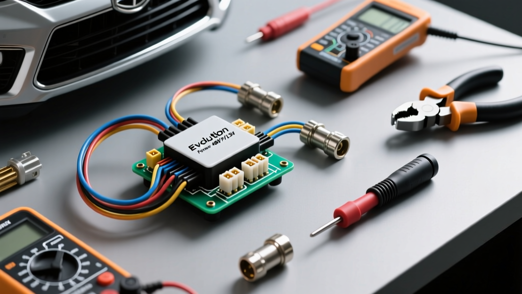
Introduction to Evolution Forester LSV Electrical Systems
The Evolution Forester series of Low Speed Vehicles (LSVs) and street-legal golf carts represent a significant leap in electric mobility, utilizing advanced 48V and 72V lithium-ion battery management systems (BMS) paired with high-efficiency AC motor controllers. When diagnosing a dead cart, erratic throttle response, or a parasitic electrical draw, the evolution forester wiring diagram is your primary roadmap. However, simply possessing the schematic is not enough. Interpreting these diagrams and executing repairs requires specialized diagnostic equipment and specific wire termination tools.
Approaching an EV electrical system with standard automotive tools often leads to misdiagnosis, damaged logic boards, or severe safety hazards. This comprehensive cost and tool requirements analysis breaks down exactly what you need to budget for when troubleshooting, repairing, or modifying the electrical architecture of an Evolution Forester, ensuring your investment in tools pays for itself on the very first repair.
Essential Diagnostic Tools for the Evolution Forester Wiring Diagram
Unlike traditional internal combustion engine (ICE) vehicles that rely on 12V CAN-bus networks, the Evolution Forester operates with high-current traction circuits (up to 400A peak) and sensitive 5V logic circuits. Your toolkit must bridge this gap safely.
Digital Multimeters & Load Testers
A standard $15 multimeter is insufficient and potentially dangerous for 72V nominal (which can peak at 84V fully charged) systems. You require a True RMS Digital Multimeter rated for at least CAT III 1000V or CAT IV 600V. Furthermore, testing the Motor Controller Operating Request (MCOR) or throttle circuit requires a meter capable of reading rapid PWM (Pulse Width Modulation) signals and precise millivolt drops. For high-current circuits, a dedicated carbon pile load tester or a clamp meter with a 600A DC capacity is mandatory to verify the health of the 2 AWG battery cables under load.
Crimping & Termination Equipment
The evolution forester wiring diagram frequently references Anderson SB175 power connectors for battery and motor connections, alongside Molex Mini-Fit Jr. or Deutsch DT connectors for the controller logic harness. Standard pliers will destroy these terminals, leading to high-resistance connections that melt under amperage loads. You must invest in a dedicated Anderson contact crimper (capable of handling 2 AWG to 1/0 AWG wire) and a precision ferrule crimper for logic board spade terminals.
Material & Tool Cost Breakdown: Rewiring & Repair Budget
Before ordering replacement parts, you must establish your baseline tooling and material budget. The table below outlines the essential items required for professional-grade diagnostics and repairs on Evolution Forester platforms.
| Tool / Material | Specification / Rating | Estimated Cost (USD) | Primary Application |
|---|---|---|---|
| True RMS Digital Multimeter | CAT III 1000V / CAT IV 600V | $150 - $300 | Logic circuits, DC-DC output, BMS comms |
| Anderson SB175 Crimper | AWG 2 to 1/0, Ratchet Release | $65 - $110 | Main battery bank & motor phase wires |
| SAE J1128 Primary Wire Kit | 18 AWG to 10 AWG, Copper | $45 - $75 | Accessory rewiring, F/R switch, lighting |
| Adhesive-Lined Heat Shrink | 3:1 Ratio, Marine Grade | $25 - $40 | Weatherproofing 12V accessory splices |
| Controller Breakout Box | Navitas / Curtis Compatible | $120 - $180 | Isolating logic faults from harness faults |
| DC Clamp Meter | 600A DC Minimum | $80 - $150 | Measuring motor phase & solenoid draw |
Total Initial Investment: $485 - $855. While this may seem steep for a DIY enthusiast, a single misdiagnosed controller replacement at a dealership can cost upwards of $1,200 in parts and labor, making this toolkit immediately cost-effective.
Navigating the Diagram: High-Current vs. Logic Circuits
When analyzing the evolution forester wiring diagram, it is crucial to mentally separate the high-current traction system from the low-voltage logic and accessory systems. Mixing up wire gauges or misinterpreting pinouts between these two domains is the most common cause of catastrophic electrical failure.
The Traction Circuit: Solenoid and Motor Phase
The main solenoid (typically an Albright SW80 or White-Rodgers 586-series contactor) acts as the bridge between the battery pack and the motor controller. The wiring diagram will show heavy 2 AWG or 1 AWG cables routed through the solenoid's high-current studs. A critical, often overlooked component in this circuit is the pre-charge resistor (usually 470 ohms, 2W). This resistor bypasses the main contacts to slowly charge the controller's internal capacitors before the solenoid fully engages. If your diagram troubleshooting reveals a welded solenoid contact, the pre-charge resistor is almost certainly burnt out. Replacing the $15 resistor saves you from replacing a $65 solenoid and potentially a $900 controller.
The Logic Circuit: MCOR (Throttle) Pinout
The MCOR is the most frequent failure point in Evolution Forester carts due to its mechanical nature and exposure to moisture. The wiring diagram details a 3-wire harness connecting the MCOR to the controller's logic board. Standard pinouts are:
- Pin 1 (Red): 5V Reference from the controller.
- Pin 2 (Black): Logic Ground.
- Pin 3 (White/Green): Signal Return (Sweeps from 0.8V at rest to 4.2V at full throttle).
Using your True RMS multimeter, back-probe Pin 3. If the voltage jumps erratically or fails to return to 0.8V when the pedal is released, the controller will engage the High Pedal Disable (HPD) safety feature, rendering the cart immobile. Replacing the MCOR requires 18 AWG SAE J1128 compliant wire and precise Deutsch or Molex crimping.
Accessory Power: The DC-DC Converter
The Forester's 12V lighting, horn, and USB accessories are powered by a DC-DC step-down converter. The diagram shows a heavy 6 AWG or 8 AWG input from the main battery positive (protected by a 50A fuse) and a 10 AWG output to the 12V fuse block. A common diagnostic error is testing the DC-DC converter under no load. You must use a load tester to draw at least 15A while monitoring the output; a failing converter will show 13.8V at rest but drop below 11V under load, causing the cart's LED headlights to flicker and the horn to sound anemic.
Common Failure Modes & Diagnostic Cost Savings
Understanding the real-world failure modes of the Evolution Forester allows you to leverage the wiring diagram to save significant money. Below is a diagnostic decision tree comparing dealership assumptions vs. precise diagram-based troubleshooting.
- Symptom: Cart clicks once when pedal is pressed, but does not move.
- Dealership Assumption: Fried motor controller. Cost: $950+.
- Diagram-Based Diagnosis: Use the clamp meter on the 2 AWG motor phase wires. If current spikes to 400A instantly and the voltage at the controller B+ terminal drops below 40V, the issue is high internal resistance in the battery pack or a corroded Anderson SB175 connector, not the controller. Cost to fix: $25 for contact cleaner and re-crimping.
- Symptom: 12V accessories work, but the cart throws a throttle error code.
- Dealership Assumption: Replace entire wiring harness and MCOR. Cost: $300+.
- Diagram-Based Diagnosis: Back-probe the 5V reference wire (Pin 1) at the controller side of the harness. If 5V is present at the controller but only 3.2V reaches the MCOR, you have a voltage drop in the 18 AWG wire due to a corroded inline bullet connector. Cost to fix: $2 for a new butt splice and heat shrink.
Labor vs. DIY Cost Analysis
Mobile EV mechanics and specialized golf cart dealerships typically charge between $95 and $145 per hour for electrical diagnostics. Because tracing a fault using the evolution forester wiring diagram often involves removing body panels, testing continuity across 15-foot harness runs, and performing voltage drop tests under load, a standard diagnostic fee can easily reach $300 before any parts are even ordered.
By investing in the $500 tool kit outlined above, a DIY technician can perform the exact same Curtis or Navitas controller diagnostics in their own garage. Furthermore, possessing the proper crimping tools ensures that your repairs meet OEM standards, preventing the dreaded 'comeback' where a poorly crimped 2 AWG wire melts its insulation and shorts against the chassis frame—a mistake that can result in a total loss of the vehicle due to lithium battery thermal runaway.
Authoritative References & SAE Standards
When modifying or repairing the Evolution Forester electrical system, always adhere to established automotive and marine electrical standards to ensure safety and longevity. For low-tension primary wiring, refer to the SAE J1128 Standard, which dictates insulation thickness and temperature ratings for general automotive use. For circuits routed near the battery enclosure or in enclosed under-seat compartments, ensure your wiring and terminal boots meet SAE J1171 ignition protection standards to prevent arcing in the presence of off-gassing. Finally, always consult the specific Albright International contactor datasheets for precise torque specifications on high-current solenoid studs, as under-torqued 2 AWG lugs are the leading cause of electrical fires in modified LSVs.