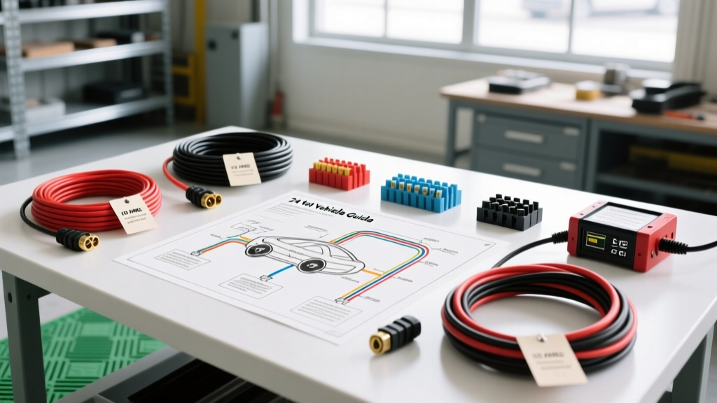
The 12V to 24V Tow Vehicle Dilemma
Integrating a marine battery bank with an automotive electrical system is one of the most common, yet frequently botched, modifications in the off-road and fishing truck communities. When you are running a high-thrust trolling motor (such as a Minn Kota Terrova or Garmin Force), you are operating on a 24V nominal system comprising two 12V deep-cycle batteries wired in series. However, your tow vehicle—whether a Ford F-150, Chevy Silverado, or Toyota Tacoma—operates on a 12V nominal alternator system outputting roughly 14.2V to 14.8V.
This voltage mismatch creates a critical engineering hurdle: you cannot charge a 24V battery bank directly from a 12V vehicle alternator. A 24V lead-acid or lithium iron phosphate (LiFePO4) bank requires a charging voltage between 28.4V and 29.2V. Attempting to wire a standard 7-way RV trailer plug directly to a 24V series bank will result in severe undercharging, sulfation, and eventual battery failure. To solve this, you need a specialized wiring diagram for 24 volt trolling motor setups that incorporates a 12V-to-24V DC-DC step-up charger.
Component Selection: DC-DC Step-Up Chargers vs. Passive Isolators
Many amateur wiring guides incorrectly suggest using a passive battery isolator or a standard 12V automotive relay. This is fundamentally incorrect for 24V series banks. Below is a comparison of the primary methods for routing tow vehicle power to a 24V marine setup.
| Component Type | Example Models | Functionality | Verdict for 24V Systems |
|---|---|---|---|
| Passive Isolator | Cole Hersee 48060 | Prevents parasitic draw between batteries. | FAIL: Cannot step up 14V to 28V. Will not charge a 24V bank. |
| 12V-to-12V DC-DC | Renogy 40A, Redarc BCDC | Regulates 12V alternator output to 12V LiFePO4/AGM. | FAIL: Output voltage is too low for a 24V series bank. |
| 12V-to-24V DC-DC | Victron Orion-Tr Smart 12/24-15 | Boosts 12V input to 24V+ output with multi-stage charging. | PASS: The only safe, effective method for tow vehicle charging. |
The Victron Orion-Tr Smart Manual outlines how their 12/24-15 model pulls roughly 30A from your truck's 12V system and steps it up to deliver 15A at 28.4V to your trolling motor batteries. This is the gold standard for our wiring schematic.
The Wiring Diagram for 24 Volt Trolling Motor Tow Integration
Because standard 7-way trailer connectors (Pin 4: 12V Auxiliary, Pin 1: Ground) are limited to 30A-40A and suffer from massive voltage drop over a 20-foot trailer harness, a dedicated auxiliary circuit is required. We utilize an Anderson Powerpole SB50 bypass circuit routed through the truck's firewall and bed.
Circuit Path & Pinout Specifications
- Power Source: Truck Starter Battery Positive Terminal.
- Primary Fusing: 60A Class T or Mega Fuse (mounted within 7 inches of the battery positive post).
- Input Wiring: 6 AWG Tinned Copper Welding Cable routed to the engine bay.
- DC-DC Charger Input: Victron Orion 12/24-15 Positive and Negative terminals.
- Ignition Sense: Tapped into a 12V ignition-switched fuse (e.g., wiper or radio fuse) using an add-a-circuit. This ensures the DC-DC charger only engages when the truck is running, preventing alternator drain.
- DC-DC Charger Output: 10 AWG Marine-Grade Duplex Wire routed through the truck bed grommet.
- Vehicle-Side Connector: Anderson SB50 (Grey Housing, 24V Standard).
- Trailer-Side Connector: Anderson SB50 (Grey) mating to the trailer's 24V charge bus.
Wire Gauge Sizing and Voltage Drop Calculations
When designing a wiring diagram for 24 volt trolling motor charging systems, voltage drop on the input side of the DC-DC charger is the most common point of failure. If the 12V input drops below 11.5V under load, the Victron Orion will trigger a low-voltage shutdown, halting the charge. SAE J1128 standards dictate strict parameters for low-tension primary cable, but for high-amperage DC-DC charging, we must oversize the wire.
| Circuit Segment | Voltage | Max Current | Distance (One Way) | Recommended AWG |
|---|---|---|---|---|
| Truck Battery to DC-DC Input | 12V Nominal | 35A | 10 - 15 Feet | 6 AWG (or 4 AWG for >15ft) |
| DC-DC Output to SB50 Connector | 24V Nominal | 15A | 10 - 15 Feet | 10 AWG |
| Trailer Harness to Battery Bank | 24V Nominal | 15A | 15 - 20 Feet | 10 AWG |
| Trolling Motor to Battery Bank | 24V Nominal | 50A (Surge) | Varies by Boat | 6 AWG (Min) / 4 AWG (Opt) |
The SAE vs. ABYC Color Code Hazard
One of the most dangerous aspects of integrating automotive and marine electrical systems is the clash in wire color coding standards. If you are not meticulous, you will create a dead short that can melt wiring harnesses and cause electrical fires.
- Automotive (SAE J1128): Red is Positive (+), Black is Negative/Ground (-).
- Marine (ABYC E-11): Black is Positive (+), Yellow or White is Negative/Ground (-).
According to ABYC E-11 standards, using black for DC positive is standard on boats. However, when routing wires from your truck (where black is universally ground) into your boat's 24V system, this discrepancy is a massive liability.
Expert Recommendation: Abandon standard black/red wiring for the crossover harness. Use Red for 12V Positive, Blue for 24V Positive, and Yellow for all shared grounds. Apply 3:1 dual-wall adhesive heat shrink at every termination point, and label both ends of the wire with embossed brass tags or high-quality printed heat shrink.
Termination, Fusing, and Real-World Failure Modes
Even with the correct wiring diagram for 24 volt trolling motor applications, poor execution leads to system failure. Below are the most common real-world failure modes and how to engineer them out of your build.
1. Alternator Burnout from Lithium Banks
If your 24V trolling motor runs on LiFePO4 batteries, their internal BMS (Battery Management System) will accept maximum current until the bank is full. A depleted 24V lithium bank will pull the maximum 15A from the Orion charger continuously, forcing the truck's 12V alternator to output 35A+ without interruption for hours. On modern trucks with smart alternators (e.g., GM's 2019+ Silverado with stop/start), this can confuse the ECM or overheat the alternator diodes. Fix: Use the DC-DC charger's Bluetooth app to set the output current limit to 10A, and enable the 'Engine Running Detection' feature via the ignition sense wire.
2. Galvanic Corrosion at the SB50 Connector
The Anderson SB50 connector is excellent for high current, but its open-face design allows road salt and boat ramp water to bridge the pins. Fix: Use dielectric grease on the pins and install a neoprene SB50 dust cover. Furthermore, ensure you are using tinned copper ring terminals, not bare copper, anywhere near the marine environment.
3. Ground Loop Noise in Sonar Units
If you share the negative bus between the 24V trolling motor and your 12V fish finder/sounder, the trolling motor's PWM (Pulse Width Modulation) speed controller will inject massive electrical noise into your sonar screen. Fix: The 24V trolling motor negative must have its own dedicated ground bus, completely isolated from the 12V accessory ground bus on the boat. The DC-DC charger's negative output should tie directly to the 24V battery bank negative, not the boat's chassis.
Final System Verification
Before connecting the 24V battery bank, use a digital multimeter to verify the output of the DC-DC charger at the Anderson SB50 connector. With the truck running and the ignition sense wire active, you should read between 28.2V and 28.8V. Once verified, connect the trailer harness and monitor the battery bank voltage over a 4-hour highway drive to ensure the multi-stage charging algorithm is transitioning from Bulk to Absorption correctly.