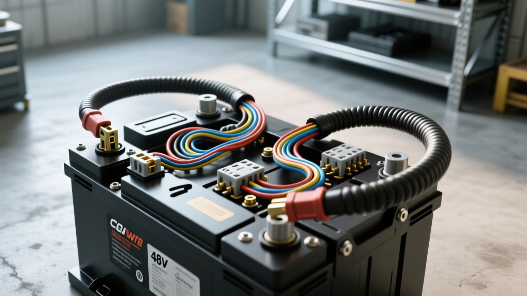
Introduction to 48V Club Car Electrical Systems
Whether you are restoring a classic Club Car DS or maintaining a modern Precedent, understanding the high-current pathways of a 48-volt electric drivetrain is critical. Many DIY mechanics search for a reliable club cart battery wiring diagram only to find vague schematics that omit crucial details like solenoid pre-charge circuits, On-Board Computer (OBC) routing, and exact terminal torque specifications. This comprehensive installation guide bridges the gap between factory service manuals and real-world garage applications. We will cover the traditional 6x8V lead-acid series circuit, proper cable routing, and the increasingly popular 4x12V lithium-ion conversion topology.
Critical Safety Protocols & Preparation
Before touching a single terminal, you must isolate the vehicle's electrical system. A 48V nominal system can deliver upwards of 400 amps under load, which is more than enough to weld a wrench to a frame rail or cause catastrophic arcing.
- Tow/Run Switch: Locate the Tow/Run switch under the passenger seat and flip it to TOW. This disables the motor controller's regenerative braking and prevents the cart from rolling away or engaging unexpectedly.
- Key & Direction: Turn the key to OFF and place the Forward/Reverse selector in the neutral position (if equipped).
- Insulated Tools: Use only VDE-rated insulated wrenches and sockets. Standard chrome sockets can easily short across battery cells if dropped.
- PPE: Wear safety glasses and acid-resistant gloves, especially when extracting older lead-acid batteries that may have micro-fractures in their casing.
48V System Specifications & Materials
To ensure minimal voltage drop and prevent thermal runaway at the terminals, your materials must meet strict automotive and marine standards. According to the SAE J1127 Battery Cable Standard, battery cables must withstand severe vibration and high-temperature engine bay environments. While a golf cart lacks an internal combustion engine, the vibration from off-road use demands equal resilience.
| Component | Specification | Notes / Application |
|---|---|---|
| Main Battery Cables | 2 AWG Copper (Class K) | Highly flexible welding cable; resists vibration fatigue. |
| Series Link Jumpers | 2 AWG Copper, 4-inch | Connects positive to negative across adjacent cells. |
| Ring Terminals | 3/8" or 5/16" Copper Lugs | Must be crimped with a hex-die hydraulic crimper. |
| Heat Shrink | Adhesive-Lined (3M or equivalent) | Prevents acid wicking into the copper strands. |
| Terminal Torque | 96 - 120 in-lbs (8-10 ft-lbs) | Per Battery Council International specs for lead posts. |
| Anti-Corrosion | Noalox or Battery Terminal Grease | Applied after torqueing to seal out moisture. |
Step-by-Step Lead-Acid Installation Guide
The standard 48V Club Car system utilizes six 8-volt deep-cycle batteries wired in series. This configuration adds the voltage of each battery while maintaining the same amp-hour (Ah) capacity as a single cell.
Step 1: Disconnect and Extract
Begin by disconnecting the main negative cable (Black) from the motor controller's B- terminal, followed by the main positive cable (Red) from the heavy-duty solenoid. Remove the battery hold-down brackets. Using a battery lifting strap, extract all six batteries. Clean the battery tray with a baking soda and water solution to neutralize any residual sulfuric acid, then rinse and dry thoroughly.
Step 2: Position and Orient
Place the new 8V batteries into the tray. Pay close attention to the terminal orientation. The batteries should be arranged so that the positive post of one battery is adjacent to the negative post of the next, minimizing the length of the series jumper cables.
Step 3: Install Series Links
Starting from the battery furthest from the main cable connections, install the 4-inch 2 AWG series links. Connect the Positive (+) post of Battery 1 to the Negative (-) post of Battery 2. Continue this alternating pattern until all five internal connections are made. Torque each connection to 110 in-lbs.
Step 4: Connect Main Power Cables
You will now have one free Negative (-) post and one free Positive (+) post.
Main Negative: Connect the 16-inch Black 2 AWG cable from the free Negative post to the Motor Controller's B- bus bar.
Main Positive: Connect the 12-inch Red 2 AWG cable from the free Positive post to the large input stud on the heavy-duty starter solenoid.
Step 5: The Pre-Charge Resistor
Many wiring diagrams omit the pre-charge resistor, but it is vital for the longevity of your motor controller. A small resistor (usually 470 ohms, 2-watt) is wired between the two large terminals of the solenoid, or integrated into the controller harness. This resistor slowly trickles current into the controller's capacitors before the main solenoid engages. Without it, the sudden 48V inrush current will cause severe arcing across the solenoid contacts and can blow the controller's internal MOSFETs. Ensure this resistor is securely wired and not pinched under battery hold-downs.
Step 6: Final Torque and Protection
Perform a final torque check on all terminals using a calibrated inch-pound torque wrench. Once verified, coat all exposed copper and terminal posts with a generous layer of Noalox or petroleum-based battery grease to prevent galvanic corrosion.
48V Lithium Conversion Wiring Variations
Upgrading to a 48V Lithium Iron Phosphate (LiFePO4) battery is the most common modern modification for Club Cars. A single 48V (nominal 51.2V) lithium battery replaces the six 8V lead-acid units, dropping over 200 lbs of weight from the chassis. However, the wiring diagram changes significantly.
Bypassing the OBC
Older Club Car DS models utilize an On-Board Computer (OBC) to regulate charging based on lead-acid voltage curves. Lithium batteries have their own internal Battery Management System (BMS). You must bypass the OBC by wiring the charge port directly to the lithium battery's main terminals, and routing the motor controller's negative trigger directly to the battery's B- output. Refer to Club Car Official Service bulletins for OBC bypass schematics specific to your IQ system year.
Charge Port and Communication
Lithium setups require a dedicated charge port and often a CAN-bus communication cable that runs from the battery BMS to the dashboard state-of-charge (SOC) meter. Never wire a standard 48V lead-acid charger to a lithium pack; the voltage cutoff parameters will trigger the BMS over-voltage protection or cause a thermal event.
Voltage Drop Testing & Troubleshooting
If your cart clicks but fails to move, or experiences severe power sag on inclines, do not immediately replace the motor controller. Perform a voltage drop test across the newly installed battery circuit.
- Static Voltage Test: Set your multimeter to DC Volts. Measure across the main positive and negative battery posts. A fully charged 48V lead-acid pack should read between 50.9V and 51.2V. A fully charged lithium pack will read 58.4V.
Dynamic Voltage Drop Test: Keep the multimeter probes on the main battery posts. Jack up the rear wheels safely, chock the front wheels, and press the accelerator pedal to engage the motor. - Analyze the Drop: If the voltage drops below 44V under load, you have high resistance in the circuit.
- Move the probes to test across each individual series jumper cable. A good cable and terminal connection should show a voltage drop of less than 0.05V.
- Any reading above 0.10V across a jumper indicates a loose terminal, a crimp failure, or internal copper corrosion requiring immediate replacement.
By adhering to these exact specifications, utilizing proper 2 AWG cabling, and respecting the solenoid pre-charge circuit, your 48V drivetrain will deliver reliable, high-torque performance for years to come. Always consult the manufacturer's specific service manual for your exact chassis year before modifying factory harnesses.